
Coop automatically fill light circuit

The circuit described utilizes a combination of components to create an effective automated lighting solution for poultry coops. The primary elements include a step-down transformer, a rectification stage, a voltage regulator, and a timing circuit. The transformer reduces the 220V AC mains voltage to a lower AC voltage suitable for rectification. The rectification stage, composed of diodes VD1-VD4, converts the AC voltage to DC, which is then filtered and stabilized to provide a steady 12V DC output using the LM7812 voltage regulator.
The light control mechanism is particularly noteworthy. The phototransistor (VTP) serves as a light sensor, which, when exposed to daylight, exhibits low resistance, preventing the transistor (VT) from conducting. This state keeps the relay (K) deactivated, ensuring that the light remains off during the day. As night falls, the ambient light decreases, leading to an increase in the resistance of VTP. This change allows the voltage at the trigger terminal of the timing circuit (A2) to drop, which activates the timer and energizes the relay. The relay then closes its contacts, turning on the fill light for the predetermined duration of approximately two hours.
The timing circuit, based on the NE555 IC, is configured to manage the duration of illumination effectively. The circuit uses a voltage divider to set a reference voltage at the trigger pin, allowing for precise control over the timing intervals. By adjusting the capacitance and resistance values in the timing circuit, the duration of the light can be modified to suit specific requirements, extending the illumination period as necessary.
Overall, this automated lighting system is designed for efficiency and reliability, ensuring that poultry receive adequate light exposure to optimize egg production, particularly during the shorter days of winter. The careful selection of components and the thoughtful design of the circuit allow for consistent performance in various environmental conditions. When implementing this system on a larger scale, such as in commercial poultry farms, the relay can be replaced with an AC contactor to manage higher power loads, ensuring the system can handle multiple lighting fixtures while maintaining safety and functionality. Proper installation of the phototransistor is crucial, requiring it to be housed in a sealed glass vial to protect it from environmental factors while allowing it to sense light effectively.Hens to provide adequate illumination can increase egg production rate, since when asked to shorten the winter sunshine, so chicken specialized households generally use artificial lights way for coop fill light. Such as the use Figure 297 day i circuit is able to automatically fill light when night comes, the light will automatically turn on the lights Park about Zh, then off, will extend the duration of sunshine is about 2 h. 220V AC by the step-down transformer T, VDI-VD4 rectification, Al [T. M7812) stable monthly magazine G, Cz filtered output stable 1 2V DC voltage for machine use. Light control circuit by the phototransistor VTP, j pole tube VT and other components. During the day, VTP exposure to light exhibits low resistance, the collector output low. VT cut-off, its collector is high. Timebase circuit A2 (NF, 555) when asked salt composition timing circuit, which triggers the end feet and connected to the R, dividing point r, the potential of higher ten 1 / 3VDD (V means J2V electric rE).
Therefore A2 is in the reset state, pin output low, the relay K is not action, E-light does not shine. At this time (, by R, R, allow electric charge to be positive the right fish. When the night comes off the mere mention of dark, VT1] equivalent resistance gradually Nine, so it was with RI 'partial pressure-point level gradually increase, when raised to a certain value, VT conduction, the collector output low level, c, namely VT and Mindanao discharge, the trigger terminal foot level A2 F quickly pulled to L / 3Vij ,, or less .
A 2 is triggered into the transient, pin goes high jump, K action la station, which is closed off contact k1, F protium lit sheds light fill light. Thereafter C, but also by R., wr reverse charge, the trigger pin electrical terminal calm original, not like the town its state coup.
then power through R, 0 charge to make ends Yin value foot level rose constantly high, when valves to the reset level, 2h timer expires, A2 resets turned back to the stable state, pin returns low, K release, light E off, when the first morning Eastern white, VTP by light resistance was low, VI off, the collector and dancing goes high, but this does not make a positive transition trigger T as A2, Chung again only at night, cross circuit can be triggered again fill light 2h. principle composed of people timer A2 is clever use of the time base feet first circuit functions to achieve, at the internal base by a voltage divider circuit has three resistors of the same resistance, the first feet on the first one connected to the first resistors of the question, the first potential feet is fixed in 2,73V..L, so the base circuit of the reset level of 2,3 V [J muscle such as raising the level of the first pin through an external circuit meters, the reset level increased, we can achieve the extension K Timing purpose of time.
Figure in VD5 positive terminal connected to the power supply and ask feet, let diode forward voltage drop of 0 65V, then the first foot level was fixed at 12-0.65 =] 1 35V. feet are low when the first contact when made, the circuit is set, the timer starts, 12V to the positive supply through R, to 'charge, so that the first pin level does not rise off, when the level rose to No.
pin state the circuit reset the timer expires. If the first feet vacant or through a small capacitor connected to ground (which is the usual connection), when the first foot level through valves feet level that is 2 / 3V .. a 8V, circuit on reset, and now you need to Shenzhen 3 5V, the circuit can be reset to turn f 1 steady, timing it so much longer.
asked about up to 2h left Ran when using data set name is shown. to change timing , you can increase or decrease c. capacitance value or R, a bundle of resistance. T with 220V / 15V, 8VA small, high quality power transformer .K with TZC-22F, DC12V small in the number of available power electromagnetic relay .E incandescent bulbs in parallel used, but the total power should be controlled at 1000W or less. If used on a large scale chicken farm. K can then drag AC contactor control lights blinking. when installed, it should be sensitive probe (VTI ') into a glass vial, leads to lead in the bottle at the glass with epoxy sealant, then install outdoor collapse under the eaves, so that it can fully experience the natural light, while snow and rain erosion can be defined.
Related Circuits
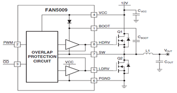
The schematic illustrates a typical application circuit for the FAN5009, a dual bootstrapped 12V high-frequency MOSFET driver. When integrated with a multi-phase PWM controller and power MOSFETs, it can form a complete core voltage regulator for microprocessors, as specified...
A voltage supply ranging from 6 V to 15 V is required when using a single LED per module. An increase in the number of LEDs necessitates a corresponding increase in the voltage supply, with additional LEDs connected in...
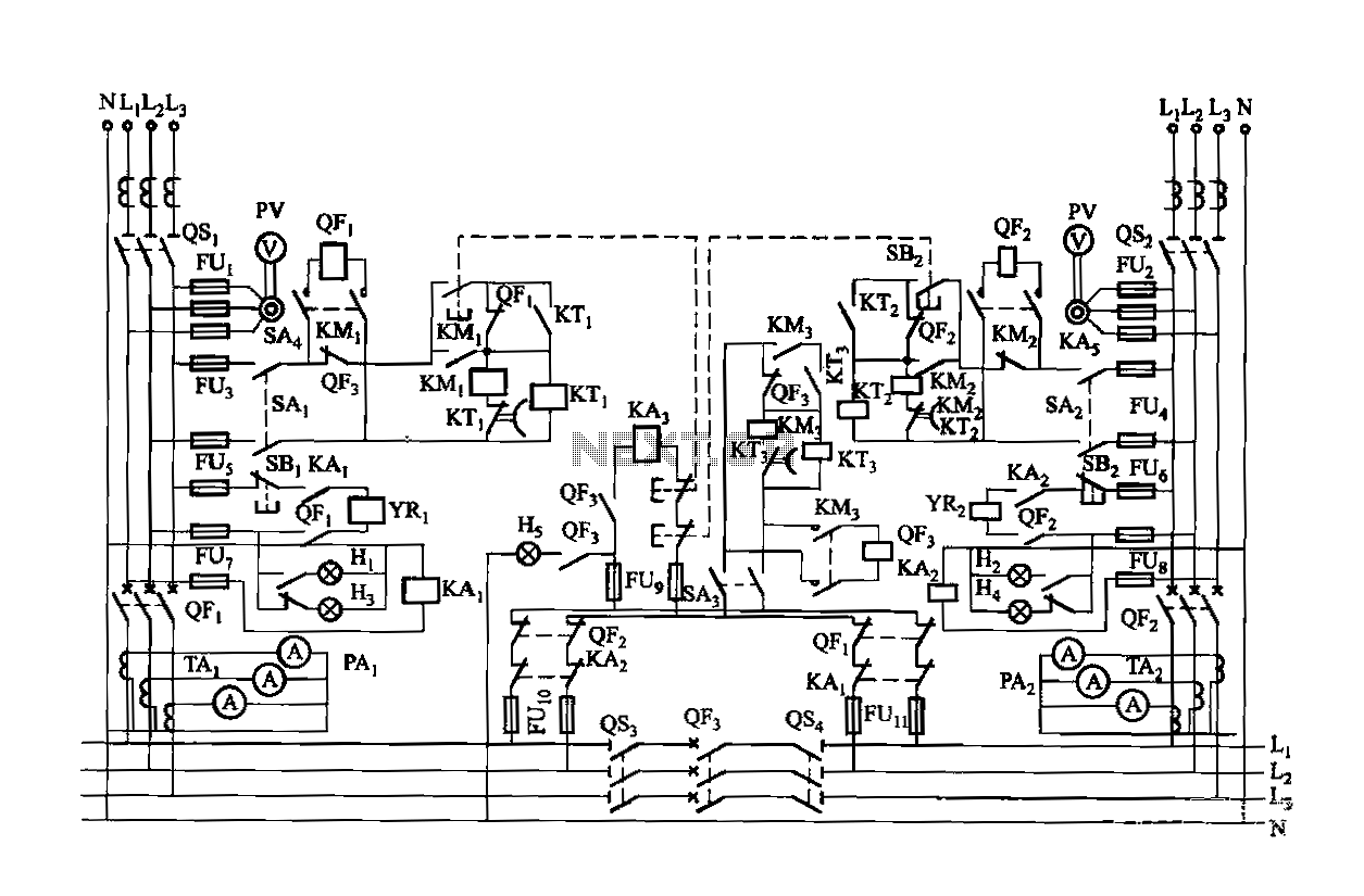
Dual power is provided for each complex, as the load is supplied through a two-way power system. In the event of a power outage, the contact switches transition from a closed position, allowing the power supply circuit to bear...
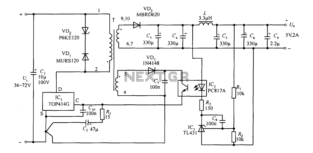
The circuit consists of a 5V TOP414G isolated switching power supply with a 2A output. C1 serves as the input filter capacitor. The circuit includes a voltage clamp protection mechanism composed of VD1. The control terminal is connected to...
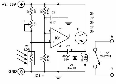
The brightness of the surrounding light controls the function of this circuit. The light sensor used in this circuit is a light-dependent resistor (LDR). This LDR is connected to the non-inverting input of the 741 op-amp IC. Once the...
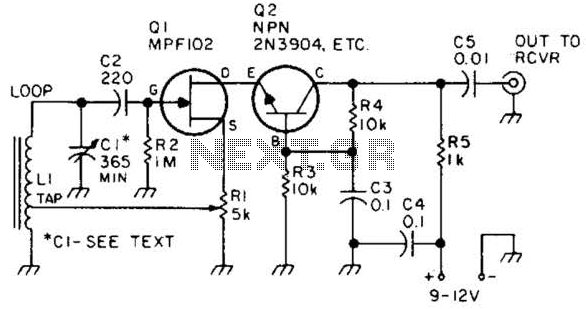
This preamplifier features a built-in regeneration control that enhances gain selectivity. CI represents a single or multi-gang AM broadcast-band tuning capacitor, while LI is a ferrite loop antenna tapped at approximately 15 to 25% of the total turns. This...