
light activated switch

This circuit operates as a light-sensitive automatic switch, leveraging the properties of a light-dependent resistor (LDR) to detect ambient light levels. The LDR exhibits a variable resistance that decreases with increasing light intensity. This characteristic is utilized by connecting the LDR to the non-inverting input of a 741 operational amplifier (op-amp), which amplifies the voltage signal derived from the LDR's resistance.
When the ambient light intensity falls below a predetermined threshold, the output of the op-amp transitions from a low state to a high state. This change is crucial for activating the transistor T1, which is configured as a switch. The conduction of T1 allows current to flow through the relay, energizing it and enabling the connected electrical load, such as a lamp, to turn on.
The circuit's versatility is highlighted by its adjustable supply voltage, accommodating a range from 10 to 36 volts, making it suitable for various applications. The inclusion of a potentiometer (P1) allows for fine-tuning of the light sensitivity threshold, with specific recommendations for street lamp applications suggesting a 50K potentiometer for P1 and a 10K resistor for R1. This adaptability ensures that the circuit can be optimized for different lighting conditions and operational requirements.
Furthermore, it is essential to select a relay with an appropriate voltage rating to ensure reliability and safety when controlling electrical loads. This circuit exemplifies an efficient solution for automatic lighting control, particularly useful in scenarios where consistent light levels need to be monitored and responded to without manual intervention.The brightness of the surrounding light controls the function of this circuit. The light sensor used in this circuit is a light dependent resistor(LDR). This LDR is connected to the non-inverting input of the 741 opamp IC. Once the intensity of the light striking the LDR sinks below the minimum level, the output of the opamp reverses from "low" to "high" level. The follow up transistor T1 conducts and the relay is activated thereby switching on any electrical load connected to the relay (for example: lamp). The most common application of this circuit is as an automatic switch for street lamps. Of course you can use it for other applications that require a circuit controlled by the surrounding light.
The supply voltage of the circuit is highly flexible. It can be between 10 and 36 volts. Potentiometer P1 adjusts the threshold level where the relay must be activated. If you intend to use this circuit to automatically control street lamps, replace P1 with 50K and R1 with 10K. The voltage rating of the relay must be selected to handle the voltage load that it is going to support.
🔗 External reference
Related Circuits
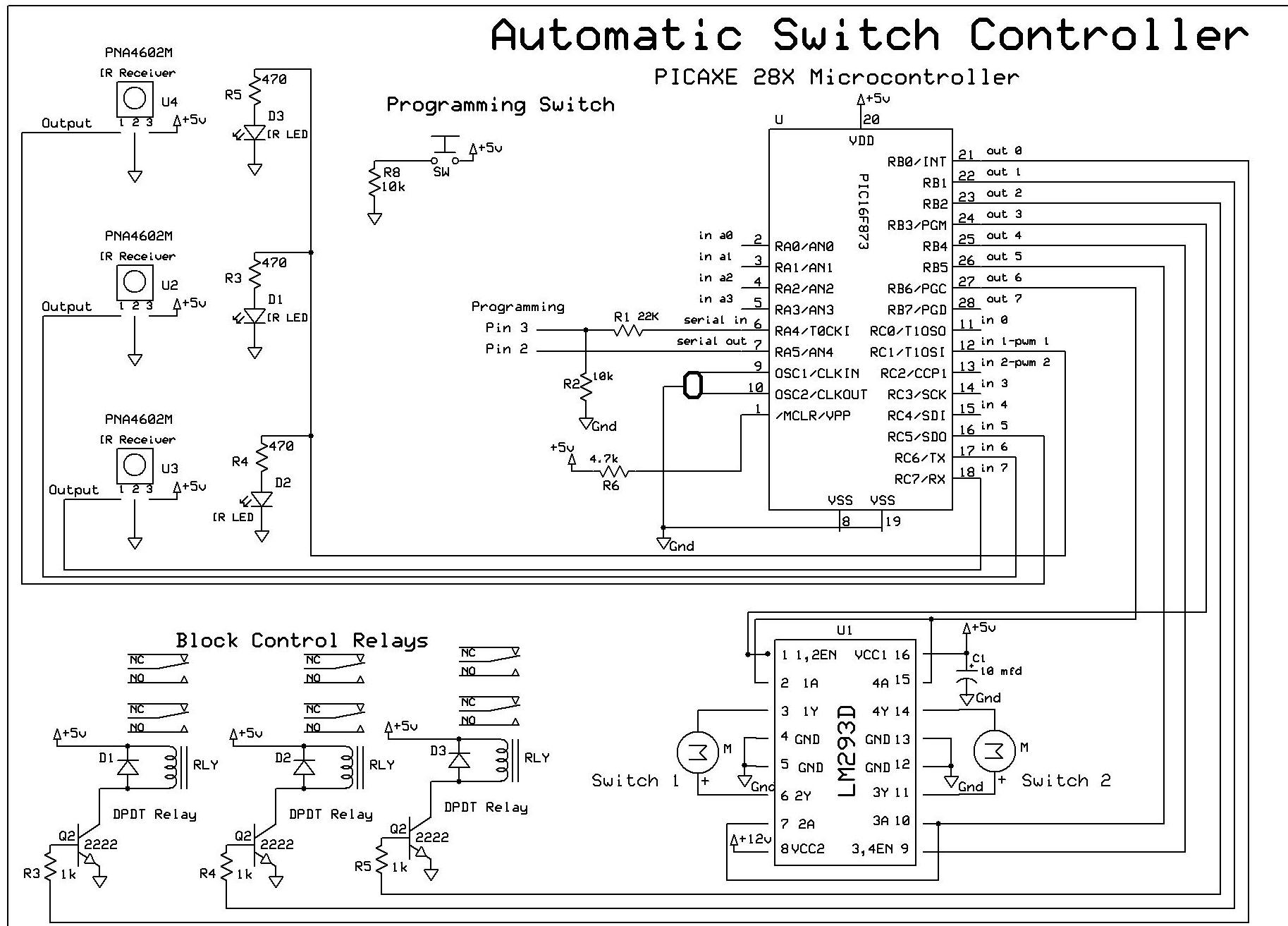
The objective of this controller project is to achieve automatic block and switch control for five separate engines operating on two independent loops of track. Each loop has both public and hidden sections. The inner loop accommodates three trains,...

The circuit on the right uses three bipolar transistors to accomplish the same result with the touch contact referenced to the negative or ground end of the supply. Since the base of a bipolar transistor draws current and the...
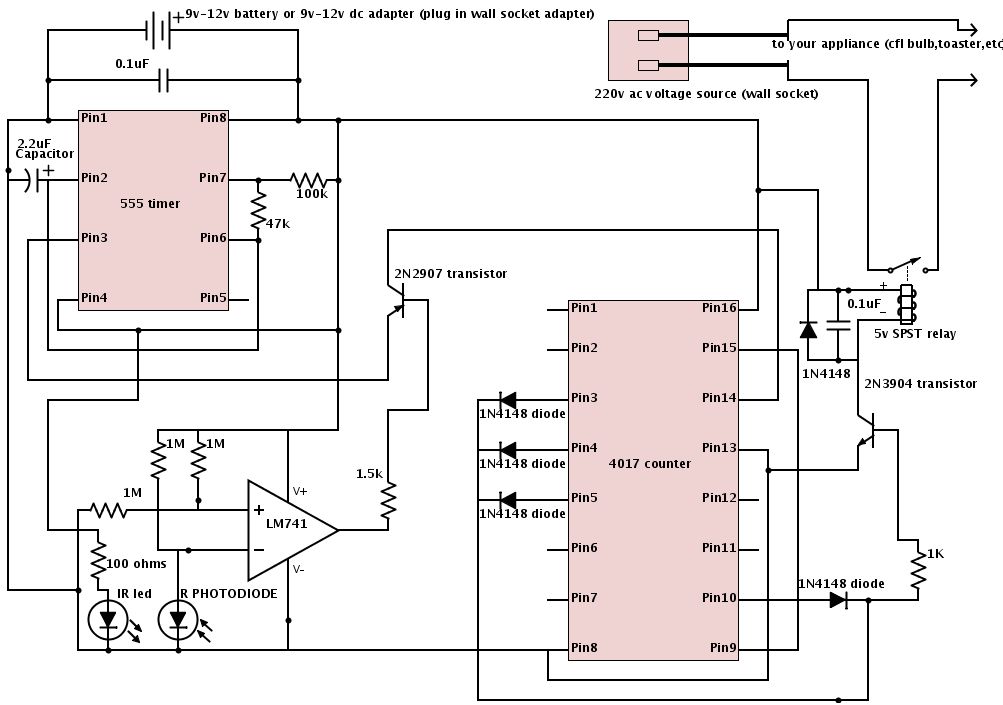
The schematic is provided below. It is recommended to construct it in three distinct sections, similar to the method demonstrated. The 555 timer circuit: connect pin 2 to pin... The schematic outlines a circuit design utilizing a 555 timer, a...
This project demonstrates a visual representation of audio volume levels through the use of LEDs that illuminate in response to music. The circuit connects to the speaker output of an audio amplifier, allowing it to gauge the audio signal's...
This is a mini strobe light. NE555 is used as a self-oscillator. The width of the output pulse is changed by the variable resistor. 25 msec means 40 Hz. 6 msec means 166 Hz. A LED is connected to...
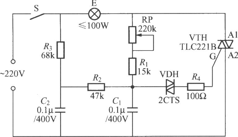
To address the lag and light transition issues, a Triac dimming light circuit featuring a dual time constant can be employed. This circuit enhances the resistor-capacitor network formed by R3 and C2. The reduced charge on capacitor C1 can...