
Counter display with led 7 segment by IC CMOS

The digital counter circuit is designed using the 4029 binary counter integrated circuit, which counts in binary and can be configured to count up or down based on external control signals. The 4029 features a parallel load capability, allowing it to be preset with a specific value, making it versatile for various counting applications.
The output from the 4029 is fed into the 4513 integrated circuit, which serves as a BCD to 7-segment decoder/driver. The 4513 translates the binary coded decimal (BCD) output from the counter into the appropriate signals needed to illuminate the segments of a 7-segment display. The 7-segment display consists of seven individual LEDs arranged in a figure-eight pattern, which can represent numeric digits from 0 to 9.
In terms of circuit connections, the 4029’s output pins are connected to the input pins of the 4513, ensuring that the binary data is correctly interpreted. Control pins on the 4513, such as the enable and blanking inputs, can be utilized to manage the display output effectively, allowing for features like turning off the display or enabling it based on specific conditions.
Power supply connections for both ICs must be ensured, typically using a regulated +5V source. Proper decoupling capacitors should be placed near the power pins of both ICs to filter out noise and ensure stable operation.
Overall, this digital counter circuit can be applied in various applications such as timers, clocks, and scoreboards, providing a clear visual representation of the counted values through the 7-segment display.This is the simple digital counter circuit, the IC application number 4029 from binary data, and then sent to the IC number 4513, a driver IC 7 Segment, to show. 🔗 External reference
Related Circuits
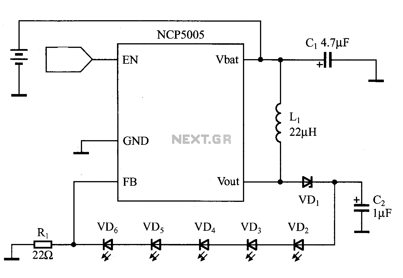
White LEDs can be connected in series or parallel, each method having its own advantages and disadvantages. A key disadvantage of the parallel connection is that the current and brightness of the LEDs do not automatically match. In contrast,...

Laptop computers frequently utilize large-screen LCDs that require both a variable and a negative supply to achieve maximum contrast. This circuit operates from the system's positive battery supply and generates a digitally variable negative voltage to drive the display....
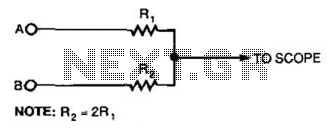
This simple resistor circuit can be used to trick an oscilloscope into displaying two logic signals on one channel. By selecting R2 to be twice the value of R, the oscilloscope trace will show one of four distinct analog...
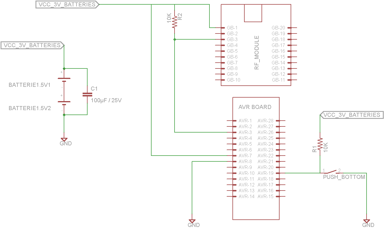
This tutorial demonstrates concepts for creating a lamp with dual actuation. The lamp can be controlled through a parallel switch or by a relay that is managed using an RF module based on the ZigBee protocol (IEEE 802.15.4). The...
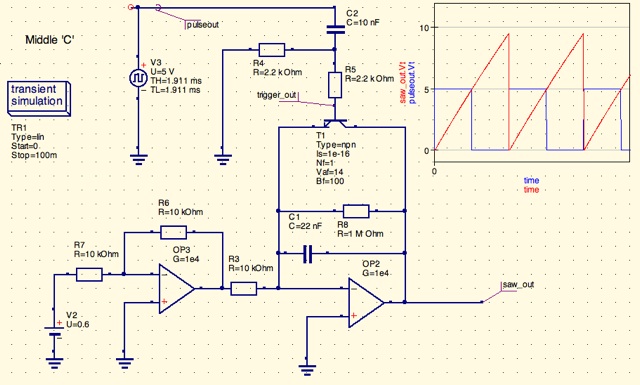
A design for a digitally controlled analog oscillator is being developed. The control voltage is generated by a microcontroller (Arduino) and is utilized through two operational amplifiers, along with a resistor and capacitor network that forms an integrator circuit....
With the recent events at the Fukushima Dai-ichi nuclear power plant, it would be interesting to build a Geiger Counter and connect it to a NerdKit for interfacing with a computer. An article detailing the building process is available,...