
Digital Levels Scope Displays 2 Logic Signals On 1 Scope
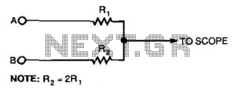
This circuit utilizes a resistor divider configuration to combine two digital logic signals, A and B, into a single output that can be visualized on an oscilloscope. The resistor values are critical in determining the resulting voltage levels displayed. By setting R2 to twice the resistance of R, the circuit can create four unique voltage levels corresponding to the logical states of A and B: both low (0V), A high and B low, A low and B high, and both high.
The voltage levels are derived from the following relationships:
- When both inputs are low (0V), the output voltage is at its lowest level.
- When A is high and B is low, the output voltage will be at a medium level determined by the resistor values.
- When A is low and B is high, the output voltage will be at another medium level.
- When both inputs are high, the output voltage reaches its maximum level.
It is essential to consider the current-sourcing capability of the digital logic driving the inputs, as this will affect how accurately the oscilloscope can display the intended voltage levels. High resistance values are required to minimize loading effects on the logic circuit, but this leads to a trade-off in frequency response. The circuit's ability to accurately represent fast-changing digital signals is limited, making it more suitable for lower frequency applications or for observing slower transitions in logic levels.
In summary, while this resistor circuit provides a useful method for visualizing multiple logic states on a single oscilloscope channel, careful consideration must be given to resistor values, the characteristics of the digital logic, and the limitations imposed by high resistance on the frequency response of the system. Using this simple resistor circuit, you can trick your oscilloscope into displayin g two logic signals on one channel. If you select R2 to be twice R, the scope trace will show one of four distinct analog levels for each possible combination of the states of inputs A and B. Of course, the voltage levels that your oscilloscope sees depends heavily on the current-sourc-ing capability of your digital logic.
Because you must use high resistances, this technique has a limited frequency range. 🔗 External reference
Related Circuits
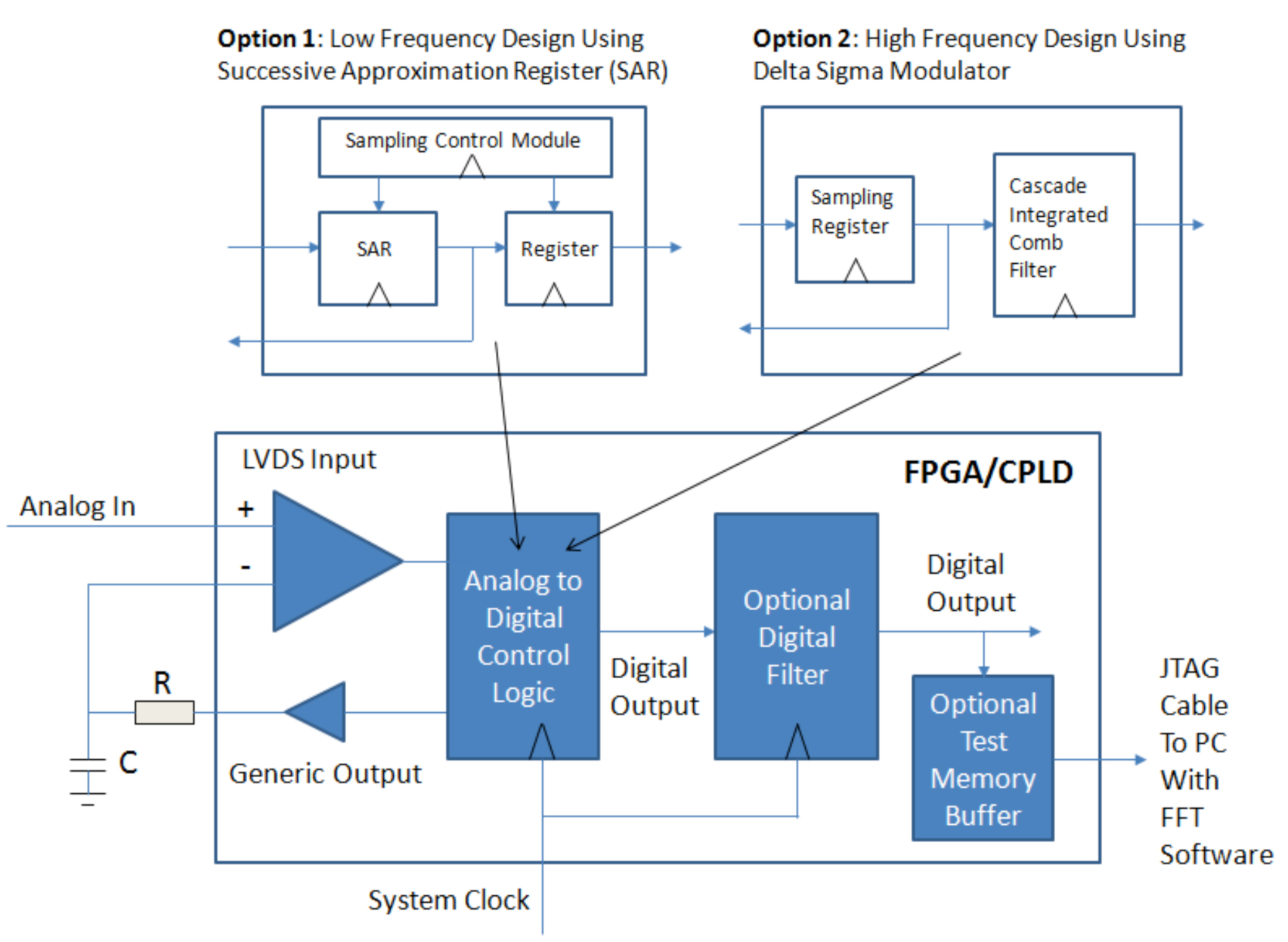
Designers of digital systems are familiar with implementing the remnants of their digital design by using FPGAs and CPLDs to connect various processors, memories, and standard function components on their printed circuit board. In addition to these digital functions,...
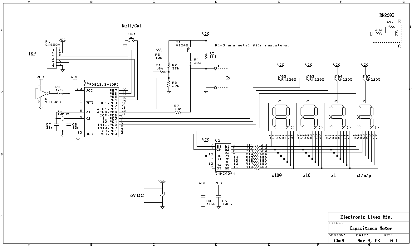
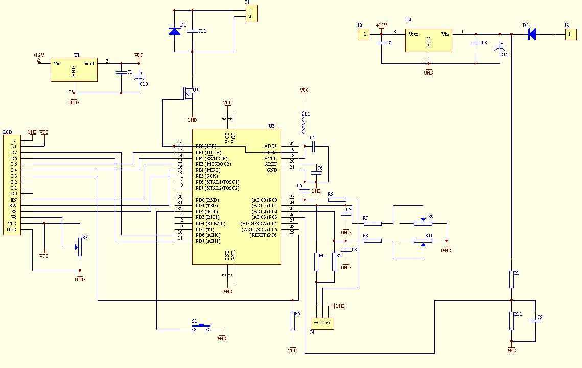
This is a simple capacitance meter which can measure capacitance value easy. There are some measurement methods for capacitance, at one time the capacitance was measured with a impedance bridge or a dip meter. Recently typical capacitance meters can...
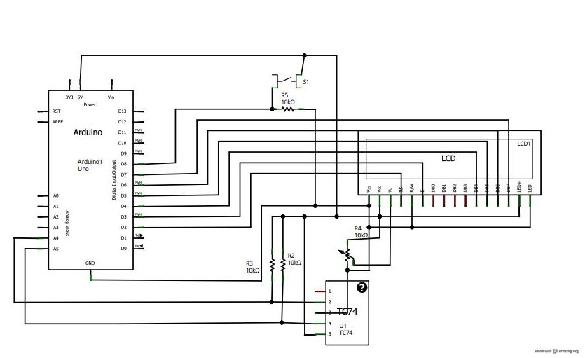
A tutorial on LCD communication was planned for a later date due to high demand. A circuit was already assembled for testing a new LCD provided by element14. The tutorial explains how communication functions with modern LCD character displays,...
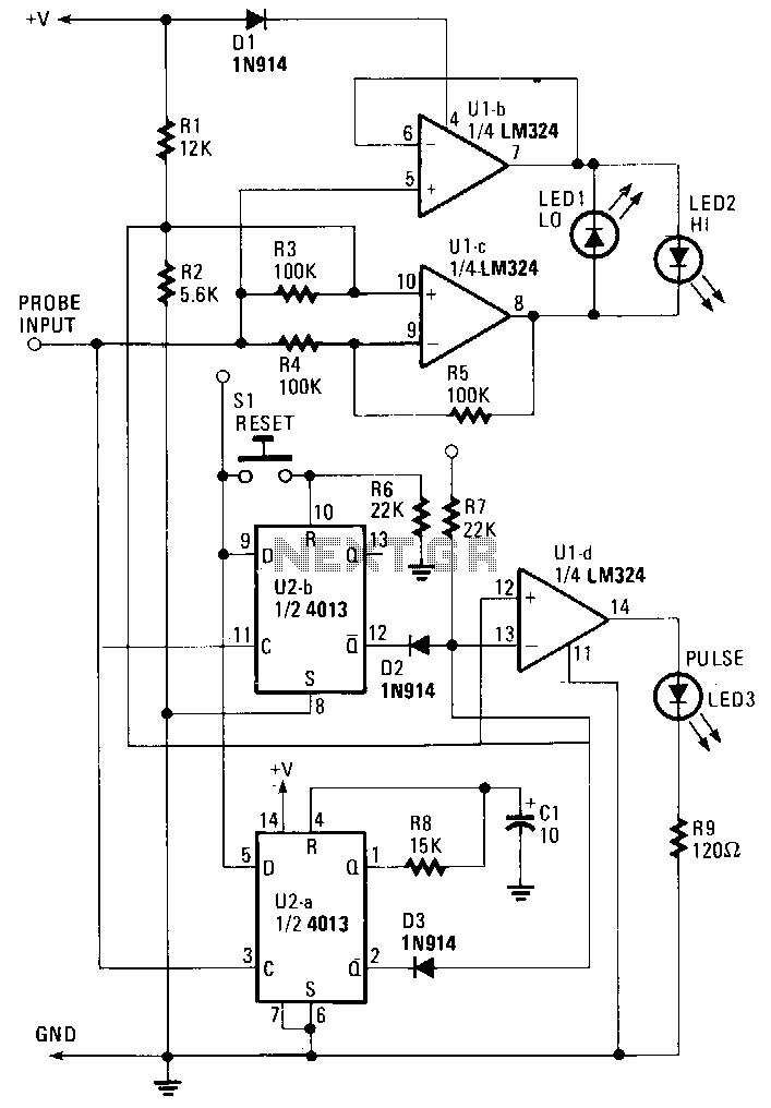
The probe operates using the power supply from the circuit under test (CUT). The input at the probe tip is divided into two pathways. One pathway directs the signal to the clock inputs of U2a and U2b. The other...
This multimeter was designed to measure output voltage and current in a PSU, where the current sense shunt resistor is connected in series with load at the negative voltage rail. It needs only one supply voltage that can be...
LED displays consist of arrays of Light Emitting Diodes (LEDs) arranged in various shapes to convey specific information. The operation of LED displays is similar to that of standard LEDs, requiring straightforward connections when sufficient microcontroller pins are available....