
Courtesy Light Extender

This circuit is designed to enhance the convenience and safety of vehicle entry and exit by extending the duration of interior lighting. The core functionality revolves around a timing mechanism that is activated when a car door is opened. Upon activation, the circuit initiates a light-emitting diode (LED) or incandescent bulb that remains illuminated for a preset interval, typically ranging from 15 to 20 seconds.
The circuit utilizes a microcontroller or a simple timer IC, such as the NE555, to achieve the desired timing function. The door switch, which is normally closed, opens when the door is unlatched, sending a signal to the timer circuit. The timer then begins its countdown, during which it powers the courtesy light.
Additionally, the circuit may incorporate a sampling feature that monitors the ambient light conditions. This feature ensures that the courtesy light only activates in low-light situations, thereby conserving battery life during daylight hours. A light-dependent resistor (LDR) can be employed to detect the ambient light level, providing feedback to the microcontroller or timer IC.
To ensure user safety and prevent the battery from draining, the circuit may include a relay or a MOSFET to handle the load of the courtesy light, allowing it to switch on and off without directly passing through the timer circuit. Furthermore, a capacitor may be included to provide a brief delay in the light extinguishing process, allowing for a smoother transition.
In summary, this courtesy light extender circuit combines a timing mechanism with ambient light sensing to provide a practical solution for enhanced vehicle illumination, ensuring that the interior of the car remains well-lit for a sufficient period after the door is opened.In essence, this circuit is a 15 to 20-second courtesy light extender for cars. It is activated in the usual way by opening a door but it also samples the.. 🔗 External reference
Related Circuits
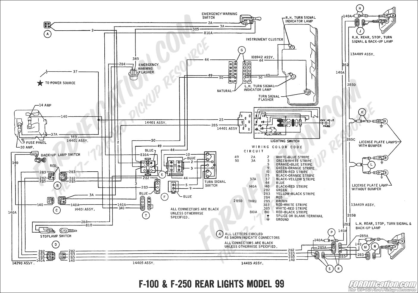
The left side of the vehicle operates correctly, with the running lights and brake light functioning properly. However, the turn signal is not working when wired directly into the harness. There is a preference to avoid purchasing a plug-in...
This simple circuit using a single transistor turns ON the relay when light falls on the LDR. The potentiometer is adjusted for the required sensitivity. The power supply is 6V. Be careful about the impedance of the relay. Its...
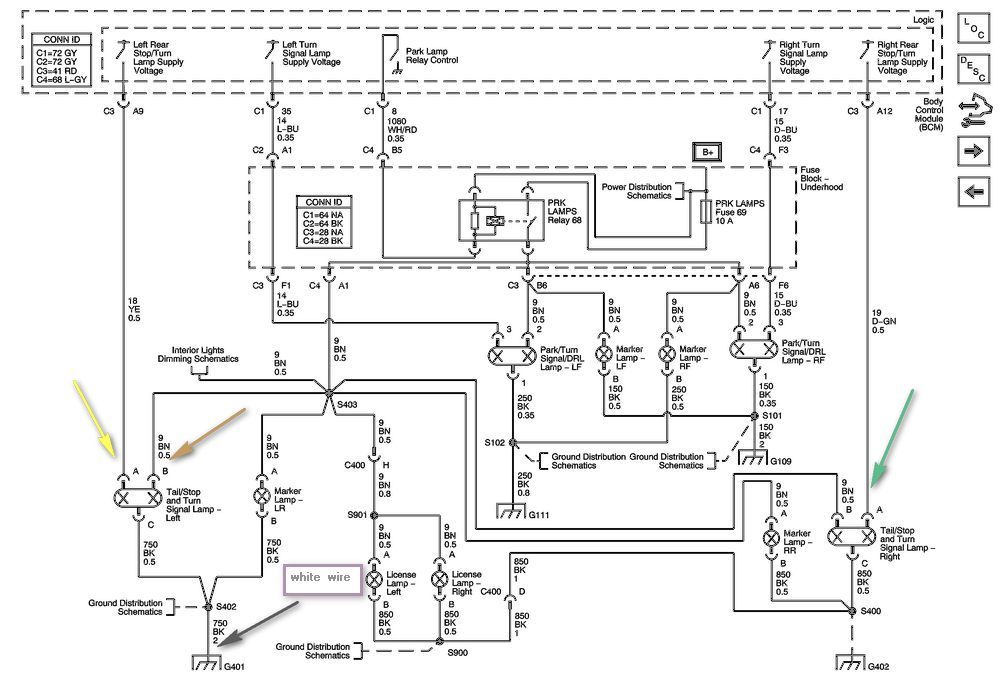
1999 Civic Wiring Diagram for Courtesy Lights Manual PDF. The 1999 Civic Wiring Diagram for courtesy lights provides a comprehensive visual representation of the electrical connections and components associated with the vehicle's interior lighting system. This schematic is essential for...
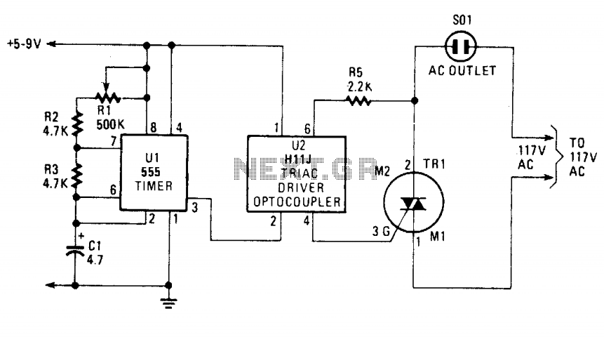
The blinking or flashing rate is determined by U1, a 555 timer integrated circuit. Its output, at pin 3, feeds U2, a H11J triac driver. That driver consists of an infrared LED that is coupled internally to a light-activated...

This simple circuit drives six LEDs in a "Knightrider scanner mode." Power consumption primarily depends on the type of LEDs used, particularly when utilizing a 7555 (the CMOS version of the 555 timer). The circuit is designed to create a...
Circuit schematics for the 555-based PLL laser light PFM receiver. Although R4 is shown as a resistor, it is advisable to replace it with a 10-kΩ precision potentiometer to allow for fine-tuning of the transmitter's center frequency. Experimentation with...