
Light Barrier Detector

This circuit employs a light-dependent resistor (LDR) in conjunction with a single transistor to control a relay, enabling it to operate based on ambient light conditions. The LDR, which exhibits a low resistance in the presence of light, is the key component that influences the transistor's state. When light falls on the LDR, its resistance decreases significantly, allowing current to flow through the base of the transistor. This action saturates the transistor, effectively turning it ON and energizing the relay coil, which in turn closes the relay contacts to power an external load.
The circuit is powered by a 6V supply, which is suitable for both the transistor and the relay operation. It is crucial to select a relay with an impedance of at least 60 ohms to ensure that the circuit functions correctly without drawing excessive current that could damage the transistor or the power supply.
A potentiometer is included in the circuit to adjust the sensitivity of the light detection. By varying the resistance of the potentiometer, the threshold at which the LDR activates the transistor can be fine-tuned. This allows for flexibility in different lighting conditions, enabling the circuit to respond appropriately to changes in ambient light.
When light is obstructed, the resistance of the LDR increases dramatically, which leads to a reduced current flow to the base of the transistor. As a result, the transistor enters a cutoff state, effectively turning OFF the relay and opening the circuit to the load. This simple yet effective design is commonly used in applications such as automatic lighting systems, alarm systems, and other devices that require light-sensitive control.This simple circuit using a single transistor turns ON the relay when light falls on the LDR. The potentiometer is adjusted for the required sensitivity. The power supply is 6V. Be careful about the impedance of the relay. Its impedance should not be less that 60ohm. Its working can be explained as follows: With the light falling on the LDR,its resistance is low and the transistor is saturated and turns the relay ON. When light is obstructed, the LDRs resistance becomes very high. The potentiometer shorts the transistors base to ground and it is cut off. Hence the relay is OFF. 🔗 External reference
Related Circuits
Moderately priced Passive Infrared (PIR) sensor modules are now widely available. By using these readymade and pre-configured PIR sensors, even an average electronics enthusiast can implement motion detection systems effectively. Passive Infrared (PIR) sensors are devices that detect infrared radiation...
This circuit should only be attempted by individuals with a strong understanding of electronic devices. It is connected to a main power source (220V) and poses a risk of high electrical shock. This circuit operates at a mains voltage of...
The circuit utilizes a 555 timer integrated circuit (IC) configured as an astable multivibrator. The flashing rate can be adjusted from very fast to a maximum of once every 1.5 seconds by changing the setting of the preset variable...
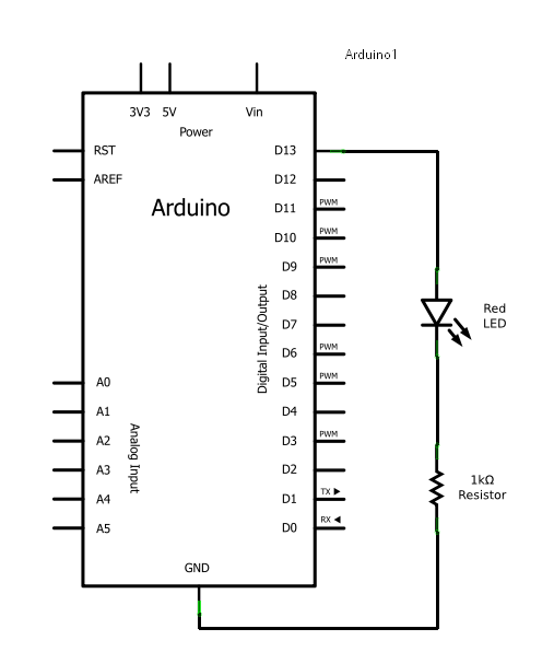
Arduino consists of two main components: the hardware (the Arduino board) and the software (the IDE). The advantage of using Arduino is that circuits can be built and their behavior modified by altering the code instead of changing the...
The report provides information related to light sensors, photoresistors, comparators, and associated circuits. It contains extensive details regarding detection. Light sensors are devices that detect and respond to light levels in the environment. A common type of light sensor is...
The metal detector circuit comprises a detection oscillator, a reference oscillator, a mixer, and a signal display, as illustrated in Figure 8-70. The detection oscillator circuit is made up of the time base oscillator IC1, inductor L1, potentiometer RP1,...