
Crank Doorbell Circuit Schematic

The crank doorbell circuit is an engaging project that combines basic electronics with practical applications. The NE555 timer, a versatile integrated circuit, is the heart of this design, providing precise timing functions. In monostable mode, it generates a single output pulse in response to a trigger signal, which in this case is provided by the crank switch mechanism. The timing interval is adjustable by changing the values of the resistor R2 and capacitor C1, allowing customization of the duration of the musical tone produced.
The use of a piezo buzzer offers an efficient way to generate sound, as it requires minimal power while producing a clear tone. The addition of diode D1 protects the timer circuit from back EMF generated by the buzzer when it is turned off, ensuring reliability and longevity of the components. The buffer capacitor C2 stabilizes the voltage supplied to the buzzer, enhancing the quality of the sound output.
In terms of the crank switch, the small DC motor acts as a generator when its shaft is rotated, producing the necessary voltage to activate the opto-coupler. The PS2505 opto-coupler isolates the timer circuit from the motor circuit, providing safety and preventing noise interference. The phototransistor's conduction state allows the timer to be triggered, demonstrating a practical application of electromechanical energy conversion.
For those looking to expand the functionality of this circuit, replacing the piezo buzzer with a relay opens up possibilities for controlling larger devices or integrating the circuit into a home automation system. The suggested 9-volt relay can switch higher power loads, making it suitable for various applications beyond just a doorbell.
Furthermore, the circuit's adaptation as a security device for two-wheelers showcases its versatility. By attaching the crank mechanism to a vehicle's wheel, the circuit can detect motion and activate an alarm, providing an additional layer of security. The recommendation for a latching output circuit in burglar alarm applications emphasizes the need for a reliable and persistent alert system, ensuring that the alarm remains active until manually reset.
Overall, this crank doorbell circuit exemplifies a fun and educational project that illustrates fundamental electronic principles while offering practical uses in everyday life.An interesting hobby circuit of a crank door bell! The circuit is built around a timer 555 and a musical piezo-buzzer. The circuit works off 9 volt battery supply. One 9volt PP3/6F22 compact battery is enough for powering the whole gadget. Timer IC (NE555) is wired in monostable mode to produce a time out o some seconds. The output of t he timer is fed to the input of the piezo sounder through a diode D1. Capacitor C2 works as a buffer. RC components R2, C1 sets the monotimeout of the timer IC NE555. An ordinary low voltage small dc motor is here used as the crank switch. In prototype, one small disc motor from a discarded cd drive (optical deck) was used. Even a slight rotation of the motor shaft will produce sufficient counter emf to enegize the LED(S) inside the ac opto-coupler PS2505. As a consequence, phototransistor inside PS2505 conducts and there by it pull down the trigger input (pin2) of IC NE555.
The result is a loud but pleasing musical tone output from the piezo sounder for a finite duration, here around seconds. One can easily replace the musical buzzer with an EM relay for switching external loads. A 9 volt/600 Ohm relay is preferred for this modification. The circuit can also be used as a two wheeler security aid which senses the wheel rotation of a parked vehicle and sounds an alarm to alert the owner.
With a little skill, one can easily attach the crank mechanism (like the dynamo-wheel assembly) to any vehicle. However, for burglar alarm application, a latching output circuit is highly recommended. 🔗 External reference
Related Circuits
The circuit utilizes a dual sound multi-frequency encoding signal to modulate the emitted carrier frequency, forming a DTMF encoding wireless calling system. It incorporates the DTMF encoding circuit UM97085 and the decoding circuit YN9101 to create a micro wireless...
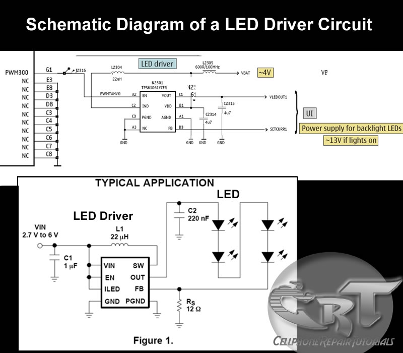
An LED (light-emitting diode) is utilized to illuminate keypad keys and LCD screen displays on all mobile phone handsets. It is controlled by the voltage or current drawn at its terminals. In the schematic diagram, the LEDs are driven...
If a complete circuit is needed, there are thousands of these circuits available in the designs. Some of them can be provided easily, but further communication is required. The request indicates a need for a comprehensive circuit design, which may...

This project was completed successfully, achieving the desired frequency and strength. For assistance, please reach out for support in resolving any issues. The project involves the design and implementation of an electronic circuit that operates at a specified frequency and...
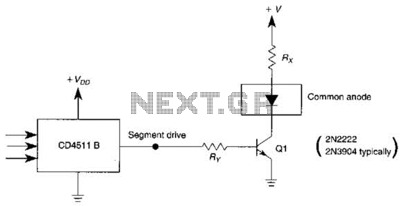
The use of a switching transistor, such as a 2N2222 or 2N3904, enables the operation of the CD4511B with a common-anode display. The transistor should be selected to provide approximately 1 mA to drive Q1, while resistor Rr must...
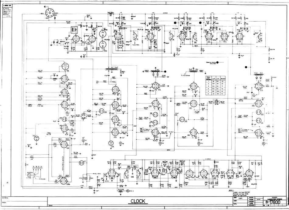
A hard copy schematic diagram related to the computer CSIRAC. The schematic diagram illustrates the detailed connections between all components in the circuit. It is used for building the circuit and later for testing. For CSIRAC, the most common...