
1.5 Watt FM Transmitter circuit

The project involves the design and implementation of an electronic circuit that operates at a specified frequency and strength, likely within the context of signal processing or communication systems. The successful execution of this project suggests a well-structured approach to circuit design, including careful selection of components, consideration of power requirements, and adherence to signal integrity principles.
Key components of such a project may include oscillators, amplifiers, and filters, which work together to generate and manipulate signals. The oscillator would be responsible for producing the desired frequency, while the amplifier would ensure the signal strength is adequate for the intended application. Filters may be employed to eliminate unwanted frequencies or noise, thus enhancing the overall performance of the circuit.
The design process typically involves schematic creation, simulation, and prototyping. Schematic diagrams serve as the blueprint for the circuit, indicating the connections between components and their respective values. Simulation tools can be utilized to predict circuit behavior before physical implementation, allowing for adjustments and optimizations to be made in a virtual environment.
Prototyping involves assembling the circuit on a breadboard or a printed circuit board (PCB) to test functionality and performance in real-world conditions. This stage is crucial for identifying any issues that may arise, such as signal distortion or power inefficiencies, which can then be addressed before final deployment.
Overall, the successful completion of this project highlights the importance of thorough planning, component selection, and testing in electronic circuit design. For those seeking assistance, expertise in troubleshooting and refining circuit designs can be invaluable in overcoming challenges and achieving desired outcomes.I MAID THIS PROJECT SUCCESSFULLY. WITH PROPER FREQUENCY AND STRENGTH. IF YOU WANT HELP THEN CONTACT ME i will surly help you to bring out you from the problem :) 🔗 External reference
Related Circuits
A DC-to-DC step-up converter is typically implemented using a transformer, which converts DC voltage to AC voltage, steps it up with the transformer, and then rectifies and filters the output to achieve a higher DC voltage. However, a voltage...
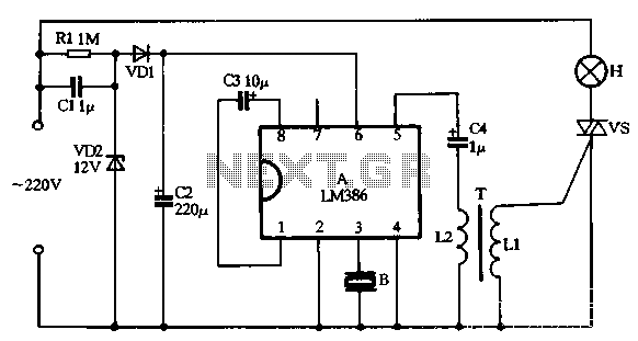
VD1, VD2, C1, and C2 comprise a simple half-wave rectifier capacitor step-down voltage regulator circuit, providing an output of approximately 12V for a linear power supply connected to the LM386. The LM386 is linked to the inverting input terminal...
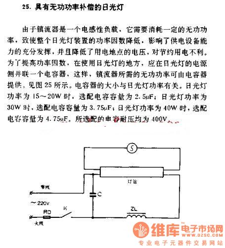
The fluorescent lamp with reactive power compensation operates with a ballast that acts as an inductive load. This inductive load requires reactive power, which leads to a decrease in the power factor of the fluorescent lamp. A lower power...
This is a small but quite powerful FM transmitter having three RF stages incorporating an audio preamplifier for better modulation. It has an output power of 4 Watts and works off 12-18 VDC which makes it easily portable. It...
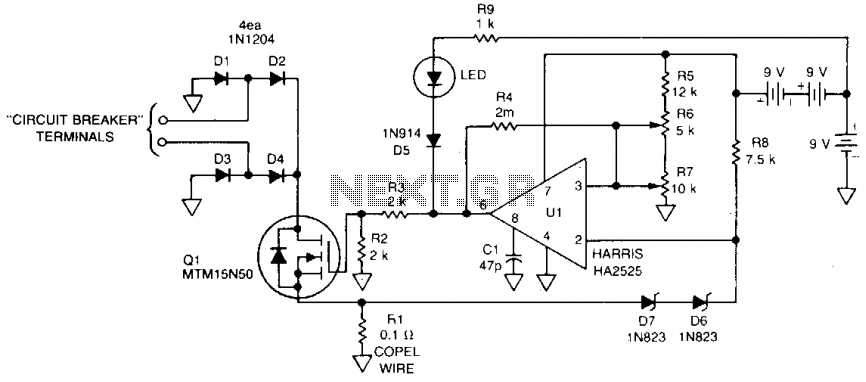
This 115 Vac electronic circuit breaker utilizes the low drive power, low on-resistance, and fast turn-off characteristics of the TMOS MTM15N50. The trip point is adjustable, and an LED fault indication is provided, with battery power ensuring complete circuit...
Artificial hatching or breeding of tropical fish requires the configuration of an oxygen pump and a circulating pump for the fish pond. Continuous operation of both pumps not only wastes energy but also risks damaging components. This example illustrates...