
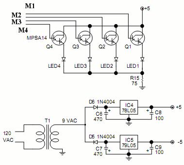
Crazy Looper Schematic

The first schematic represents a basic electronic circuit configuration that operates independently of a programming interface. This design may be suitable for applications where pre-programmed functionality is sufficient, and no further modifications or updates are anticipated after the initial setup. Such circuits often utilize fixed components, such as resistors, capacitors, and integrated circuits, which are configured to perform specific tasks without the need for external programming capabilities.
The second schematic incorporates a programming port, allowing for the reprogramming of the device after deployment. This feature is particularly beneficial in applications where adaptability and upgradability are essential. The programming port typically interfaces with a microcontroller or programmable logic device, enabling users to upload new firmware or modify existing settings. This circuit may include additional components such as voltage regulators, level shifters, and interface connectors to ensure proper communication between the programming device and the circuit.
In summary, the two schematics illustrate distinct approaches to circuit design, one optimized for fixed functionality and the other designed for flexibility and reprogrammability. Each configuration serves different operational requirements, catering to the specific needs of various electronic applications.I have included two schematics, one is the circuit without a programming port and one includes a programming port.. 🔗 External reference
Related Circuits
A video switcher circuit is required to display multiple sources on a single monitor. The circuit schematic below features the MAX454, which serves as the core component of this video switcher. The MAX454 is a video multiplexer-amplifier manufactured by...
The Boss SD-1 Super OverDrive is a pedal characterized by a straightforward design, incorporating a dual operational amplifier (uPC4558C) and six transistors, along with an asymmetric overdrive circuitry that emulates the classic, natural growl of a tube amplifier. It...
A bandpass filter passes a range of frequencies while rejecting frequencies outside the upper and lower limits of the passband. The range of frequencies to be passed is called the passband and extends from a point below the center...
Dunlop Cry Baby Wah Wah Schematic. It is challenging to replicate the Cry Baby sound due to its unique characteristics. The Dunlop Cry Baby Wah Wah pedal is renowned for its distinctive tonal qualities and is a staple in many...
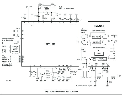
The TDA4661 is an integrated baseband delay line circuit featuring a single line delay. It is designed for use in decoders that produce color-difference signal outputs (R-Y) and (B-Y). The TDA4661 operates by delaying the baseband signal, which is essential...
This precise one-pulse-per-second clock is constructed using a few common components and is driven by a 50 or 60 Hertz mains supply, without any direct connection to it. It produces a beep or metronome-like click and/or a visible flash...