
Video Switch Circuit Schematic Diagram

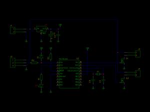
The video switcher circuit is designed to facilitate the selection of multiple video inputs for display on a single output monitor. The MAX454, a key component, functions as both a multiplexer and an amplifier, ensuring that video signals are processed with minimal degradation. It is important to maintain a well-planned signal path around the MAX454 to optimize performance. The inclusion of a ground plane between the signal channels is a recommended practice to reduce crosstalk and interference, which can adversely affect video quality.
The CD4017 decade counter serves as a sequencer that controls the activation of channel indicators, represented by LEDs (LED1-LED4). This sequencer operates by decoding a 2-bit binary signal, allowing for straightforward selection of the desired video channel. The outputs from the CD4017 not only indicate which channel is currently active but also facilitate the switching of the MAX454 multiplexer to the corresponding video input.
In designing the PCB for this circuit, it is essential to ensure that the MAX454 is soldered directly to the board to maintain signal integrity and reduce the potential for noise introduction. Proper layout techniques, including the use of ground planes and careful routing of signal traces, will enhance the overall performance of the video switcher circuit, making it suitable for applications requiring reliable video source selection.Video switcher circuit is needed to display more than one display in one monitor. Take a look at below circuit schematic : MAX454 is the core of this video. It is a video multiplexer-amplifier assembled by MAXIM Semiconductor. Pay attention when designing the video signal path around this chip. Track of ground plane can be inserted between video signal channels to prevent crosstalk and noise interference. The chip should directly soldered to the PCB. A CD4017 sequencer which drive the channel indicators (LED1-LED4) can be seen here. The output will decode 2 bit binary data by D1. D4 to address MAX454 multiplexer. The output of this sequencer also drives the indicators. 🔗 External reference
Related Circuits
To quickly determine if a remote control transmitter is functioning properly, a remote control detector can be utilized. If the remote control transmitter is operational, the detector will emit an audible alarm signal. This detector is capable of assessing...
A voltage window switch is in practice the basic lower window limit of this circuit is roughly 3V and the upper limit is 9V. The window range can be extended by fitting a suitable range Part List R1-2=10Kohm D1=9V1/ 0.5W Zener...
The circuit was originally available in kit form from a surplus supplier, but it is likely more widely accessible now. It introduces innovative concepts such as utilizing a 555 timer as a pulse width modulator (PWM) and employing serial/parallel...
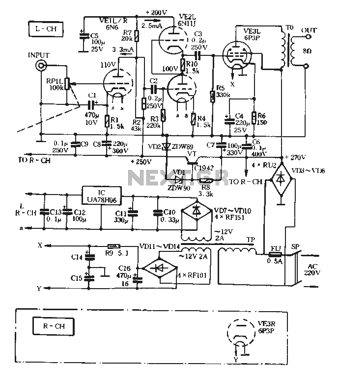
The VE1 preamplifier utilizes a low muscle, low resistance double triode 6N6 configuration, with separate halves for the left and right audio channels. The design operates within the CPI framework. It promotes the use of high-level VE2 household low...
Zilog's Z8 Encore XP F1680 Series features a highly optimized set of capabilities specifically designed for stepper motor microstepping control. Key features of the Z8 Encore! XP F1680 include: an 11 MHz internal oscillator, two analog comparators, a 10-bit...
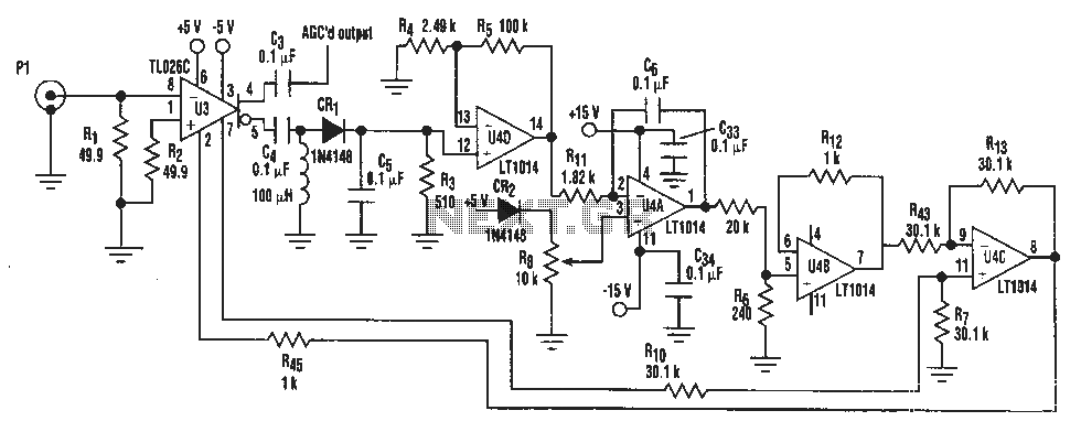
A simple IF AGC signal with a wide dynamic range and excellent linearity characteristics may be composed of two chips: the TL026C T1 voltage control amplifier IC and the LT1014 (or any other similar basic quad op amp device). The...