
Crt yoke driver

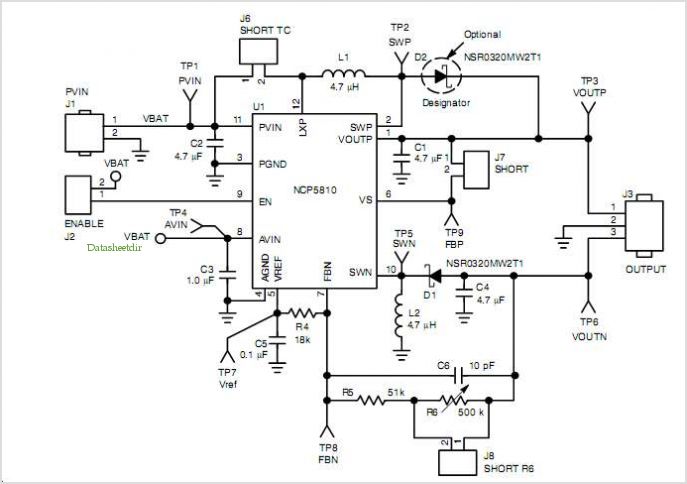
The circuit involves an amplifier configured to process a triangular waveform signal with a peak-to-peak voltage of 500 mV. This waveform oscillates symmetrically around the ground reference point, meaning that it alternates between positive and negative values, effectively creating a linear rise and fall in voltage over time. The amplifier is designed to enhance the input signal, providing sufficient gain to drive subsequent components in the circuit.
The output of the amplifier is connected to an inductor, which experiences a peak current of 100 mA. This current is a result of the amplifier's output characteristics and the inductive load's response to the triangular waveform. The inductor, due to its nature, will store energy in the magnetic field when current flows through it and will release that energy when the current decreases. The relationship between the voltage across the inductor, the current flowing through it, and its inductance can be described by the formula V = L * (di/dt), where V is the voltage across the inductor, L is the inductance, and di/dt is the rate of change of current.
In practical applications, the triangular waveform input can be used in various signal processing tasks, such as modulation or waveform generation. The resulting current through the inductor may be utilized in power supply circuits, filtering applications, or as part of a larger control system. The design considerations for this circuit include the selection of appropriate amplifier gain, bandwidth, and inductor value to ensure the desired performance and stability of the system.A 500 mV peak-to-peak triangular waveform about ground is input to the amplifier giving rise to a 100 mA peak current to the inductor.
Related Circuits
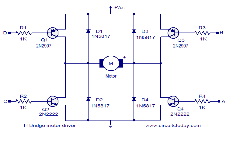
The circuit presented is a simple H-bridge motor driver circuit utilizing commonly available components. An H-bridge is an efficient method for driving motors and is widely used in various electronic projects, particularly in robotics. The circuit illustrated is a...
This design was created to address a challenge with the tailwheel doors of the P-51 Mustang. The issue arises from the complex undercarriage sequence, which would necessitate two independent sequencers. The closing sequence involves the main gear doors opening,...
A motor coil requires controllers to adjust its position and speed. A motor driver is necessary to amplify the low output current from a controller to a larger current required by the motor. The following article describes how to...
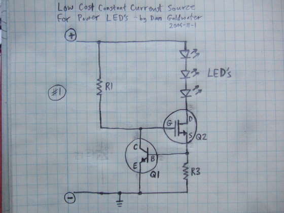
Here is a simple and cost-effective Power LED driver circuit. This power LED driver circuit is designed to efficiently drive high-power LEDs with a stable output. The circuit typically consists of a few key components: a power supply, a current...
The NE568A (NE568AD, NE568AN, SA568AD, SA568AN) is a monolithic phase-locked loop (PLL) that operates from 1Hz to frequencies exceeding 150MHz. It features an extended supply voltage range and a lower temperature coefficient of the VCO center frequency compared to...
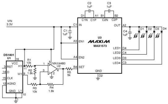
This white LED driver circuit operates up to four white LEDs in parallel from a 3.3V power source, adjusting the total LED current from 1mA to 106mA in 64 steps of 1dB each. The brightness control of the LEDs...