
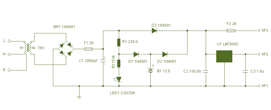
Power LED Driver Circuit

This power LED driver circuit is designed to efficiently drive high-power LEDs with a stable output. The circuit typically consists of a few key components: a power supply, a current regulator, and the LED itself.
The power supply provides the necessary voltage and current for the operation of the circuit. It is important to select a power supply that can deliver sufficient current while maintaining a stable output voltage. A common choice for such applications is a DC power supply with a voltage rating that matches the forward voltage of the LED.
The current regulator is a crucial component that ensures the LED operates within its specified current limits. This can be implemented using a linear regulator or a switching regulator, depending on the efficiency requirements of the application. For linear regulation, a transistor can be used in conjunction with a resistor to set the desired current level. In contrast, a switching regulator can offer higher efficiency and is particularly advantageous for battery-powered applications.
The LED itself should be selected based on the desired brightness and color. High-power LEDs typically require careful thermal management, so the circuit may also include a heat sink to dissipate excess heat generated during operation.
In summary, this power LED driver circuit is a fundamental design that combines a power supply, current regulation, and thermal management to effectively drive high-power LEDs, ensuring optimal performance and longevity.Here`s a really simple and inexpensive Power LED driver circuit. 🔗 External reference
Related Circuits
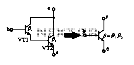
There are two composite pipe configurations: one consists of two transistors of the same type, while the other is made up of two different types of pipe configurations. The first configuration, utilizing two transistors of the same type, typically involves...
This circuit can be adapted for other regulated and unregulated voltages by using different regulators and batteries. For a 15 Volt regulated supply use two 12 Volt batteries in series and a 7815 regulator. There is a lot of...
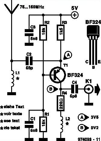
This inexpensive FM radio receiver antenna booster utilizes the BF324 TO92 style PNP transistor in a grounded-base configuration. The circuit can be employed as a... The FM radio receiver antenna booster circuit is designed to enhance the reception capabilities of...
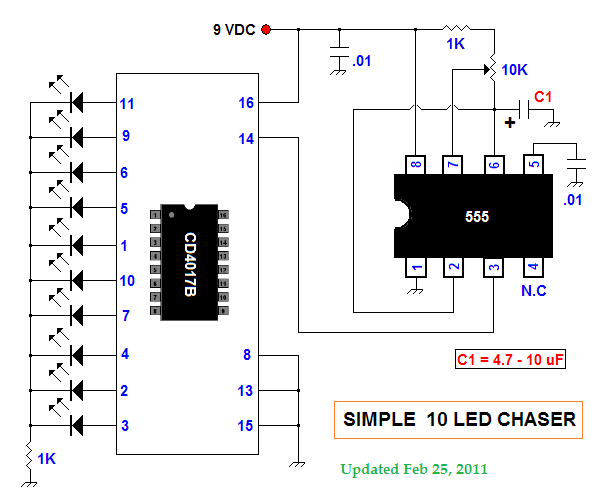
This summer, several LED projects were constructed, including sequential LED chasers that operate from left to right and a Nite-Rider style that moves sequentially left, right, left, right, and so on. These projects are enjoyable for children to experiment...
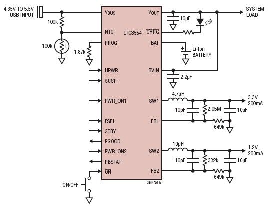
This micropower multifunction power management integrated circuit (PMIC) is designed using the LTC3554, manufactured by Linear Technology Corporation. It serves as a solution for portable Li-Ion Polymer battery-based applications. The LTC3554 integrates a USB-compatible linear PowerPath manager, a standalone...
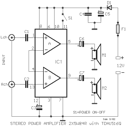
A simple stereo amplifier with minimal external components. It utilizes only one operational amplifier, which is capable of delivering an output power of 2x5W into a 4-ohm load, with a distortion of 0.5%. This stereo amplifier circuit is designed to...