
Cruise Control Removal

The cruise control system in vehicles typically consists of several key components, including the cruise control switch, the throttle actuator, the vehicle speed sensor, and the engine control unit (ECU). The wiring diagram for a cruise control system provides a visual representation of how these components are interconnected and how they communicate with each other.
In a standard cruise control setup, the cruise control switch is usually located on the steering wheel or stalk. When activated, this switch sends a signal to the ECU, which processes the input and engages the throttle actuator. The throttle actuator is responsible for adjusting the throttle position to maintain the desired speed set by the driver.
The vehicle speed sensor plays a critical role by providing the ECU with real-time data on the vehicle's speed. This information allows the ECU to make necessary adjustments to the throttle actuator to ensure that the vehicle maintains the set speed. The wiring between these components typically involves power and ground connections, as well as signal wires that transmit information between the switch, ECU, throttle actuator, and speed sensor.
To create a comprehensive wiring diagram, it is essential to include the pin assignments for each component, the color codes for the wires, and the connection points on the ECU. This information is crucial for troubleshooting and repair, as it allows technicians to identify issues within the cruise control system effectively. Additionally, safety considerations should be noted, as improper wiring can lead to malfunctioning systems that may compromise vehicle safety.
Overall, a detailed wiring diagram for cruise control in vehicles from 1994 and onward is essential for understanding the system's operation and for effective maintenance and repair.well i did a quick search, and i didnt find much on this issue my question is: Can anyone provide a diagram on how cruise control is wired up (94-.. 🔗 External reference
Related Circuits
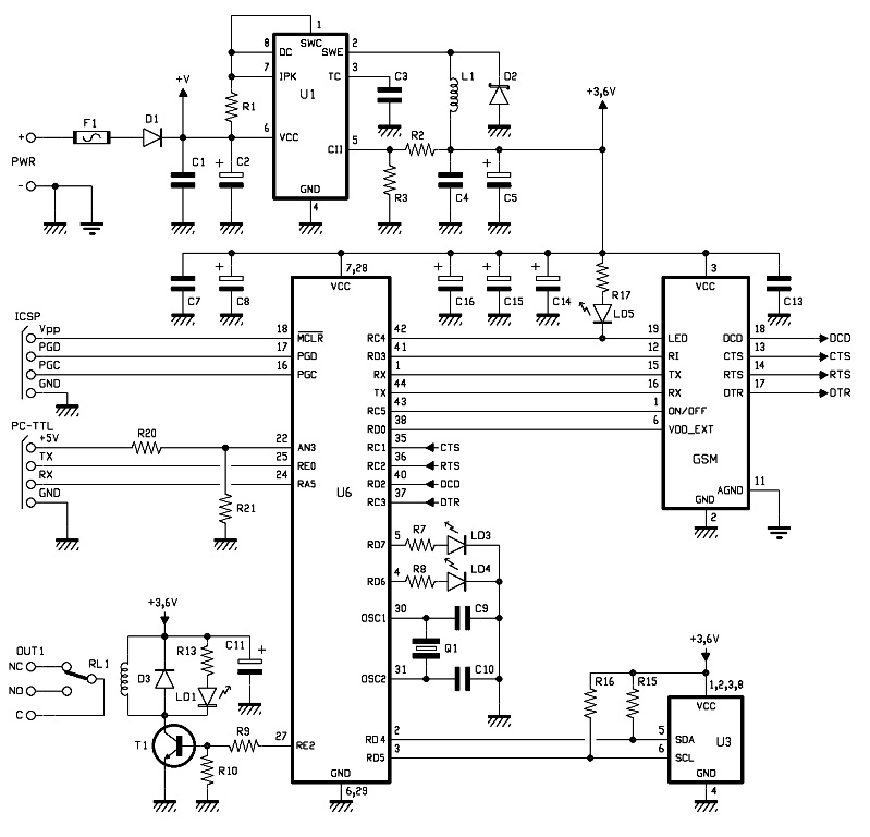
Power is supplied by continuous voltage, which is not always stabilized, applied to PWR + and - at a value between 5 and 32V. This voltage is filtered at the bottom by a diode (D1) that protects against polarity...
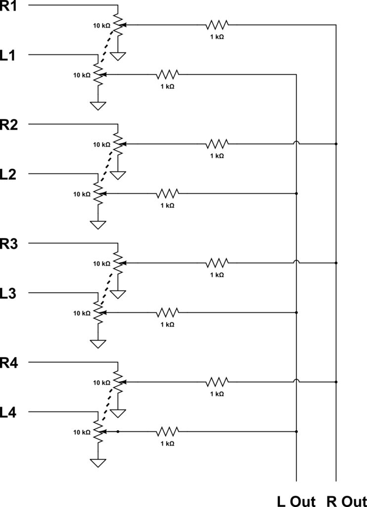
This audio mixer combines multiple audio inputs into a single audio output, equipped with knobs to adjust the volume for each channel. The specific build includes... The audio mixer is designed to facilitate the blending of various audio signals, allowing...
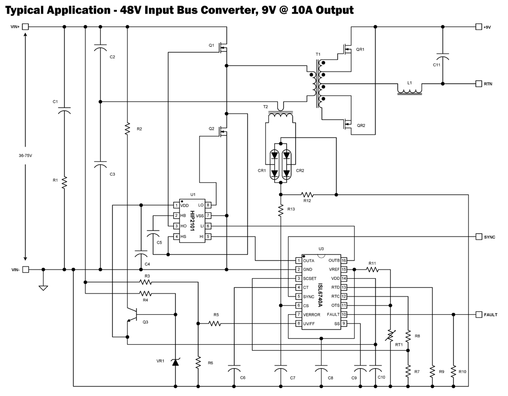
The ISL6740A is an enhanced PWM controller that incorporates built-in voltage feed forward functionality. It is pin and feature compatible with the ISL6740 double-ended pulse width modulation (PWM) voltage-mode controller, facilitating straightforward drop-in replacement in existing designs. Voltage feed...
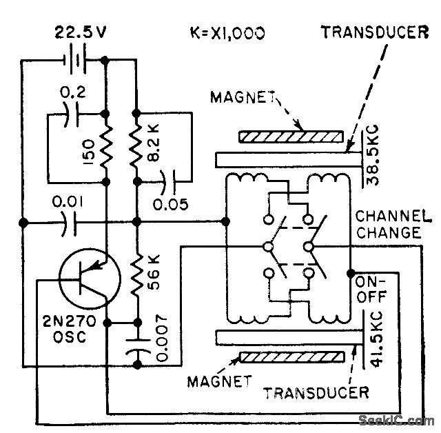
The frequency of a transistor oscillator is regulated by two different lengths of nickel tubing, each containing two coil windings. One coil functions as a driver, while the other serves as a pickup to generate feedback voltage necessary for...
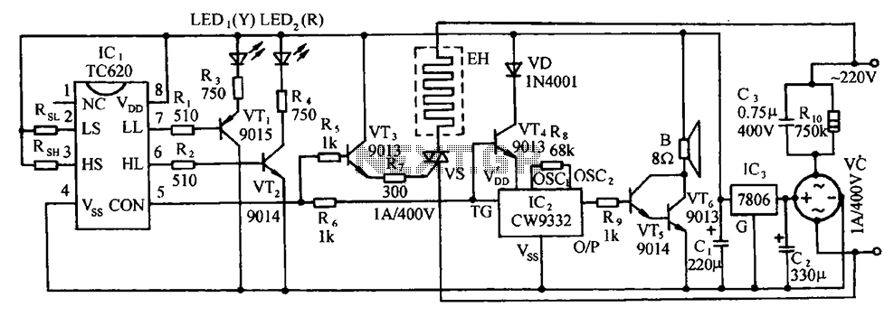
The circuit includes the TC620 temperature control circuit, the temperature indicator circuit, a thyristor-controlled heating circuit, a vocal music buck rectifier circuit, and the AC circuit. The TC620 temperature control circuit is designed to regulate temperature by monitoring the temperature...
This design is based on a publication by Milan Lulic in the German magazine elektroModell. Lulic's design utilizes surface mount technology (SMT), while this version employs standard off-the-shelf components, making it more accessible for hobbyists. For those interested in...