
TC620 temperature sensor circuit diagram of automatic heating temperature control

The TC620 temperature control circuit is designed to regulate temperature by monitoring the temperature sensor input and providing a control output. This output can be used to drive a thyristor in the heating circuit, which modulates the power delivered to a heating element based on the desired temperature setpoint. The temperature indicator circuit typically consists of a display that shows the current temperature, allowing for easy monitoring of the system's performance.
The thyristor-controlled heating circuit utilizes a thyristor to switch the heating element on and off rapidly, enabling precise temperature control. The firing angle of the thyristor can be adjusted based on the feedback from the temperature sensor, allowing for smooth control of the heating process.
The vocal music buck rectifier circuit is designed to convert AC voltage to a lower DC voltage, suitable for powering audio applications. It typically includes a transformer to step down the voltage, followed by a rectification stage using diodes to convert the AC signal to DC. The output is then filtered to provide a stable DC voltage for audio equipment.
The AC circuit is essential in providing the necessary power supply for the entire system. It connects to the mains and ensures that all components receive adequate voltage and current for operation. The integration of these circuits allows for a comprehensive system capable of temperature regulation and audio processing, making it suitable for various applications where precise control and monitoring are required. Circuit is shown. It includes the TC620 temperature control circuit, the temperature indicator circuit, thyristor controlled heating circuit, vocal music buck rectifier circuit and the AC circuit.
Related Circuits
The capacitor filter operates by measuring the capacitance, which is proportional to the pulse width. This measurement is compared to a nominal capacitance to determine qualification. The circuit, as illustrated in the accompanying figure, includes IC1 along with resistors...
An operational amplifier such as the NE5532 should be used. The desired frequency must be calculated for each block: one for flat, one for bass, and one for high frequencies. It is important to include a buffer at the...
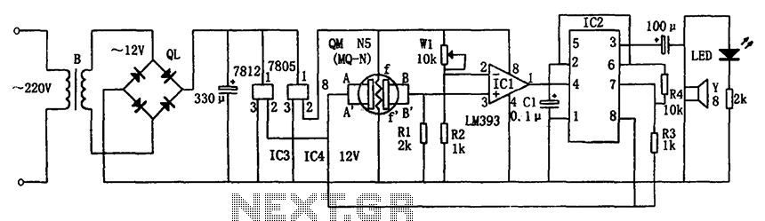
The circuit consists of a buck rectifier and voltage regulator, a gas sensor, a comparator circuit, and an alarm sound circuit. The buck regulator circuit includes a transformer, a bridge rectifier, and components such as QL, IC3 (7812), and...
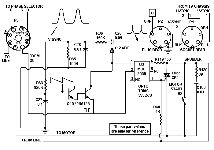
Despite the high impedance of its inputs, the Darlington transistor Q10 generates sufficient current to drive an LED. The inverted output of Q10 powers the internal LED of opto isolator U5, which, in turn, couples to the motor control...
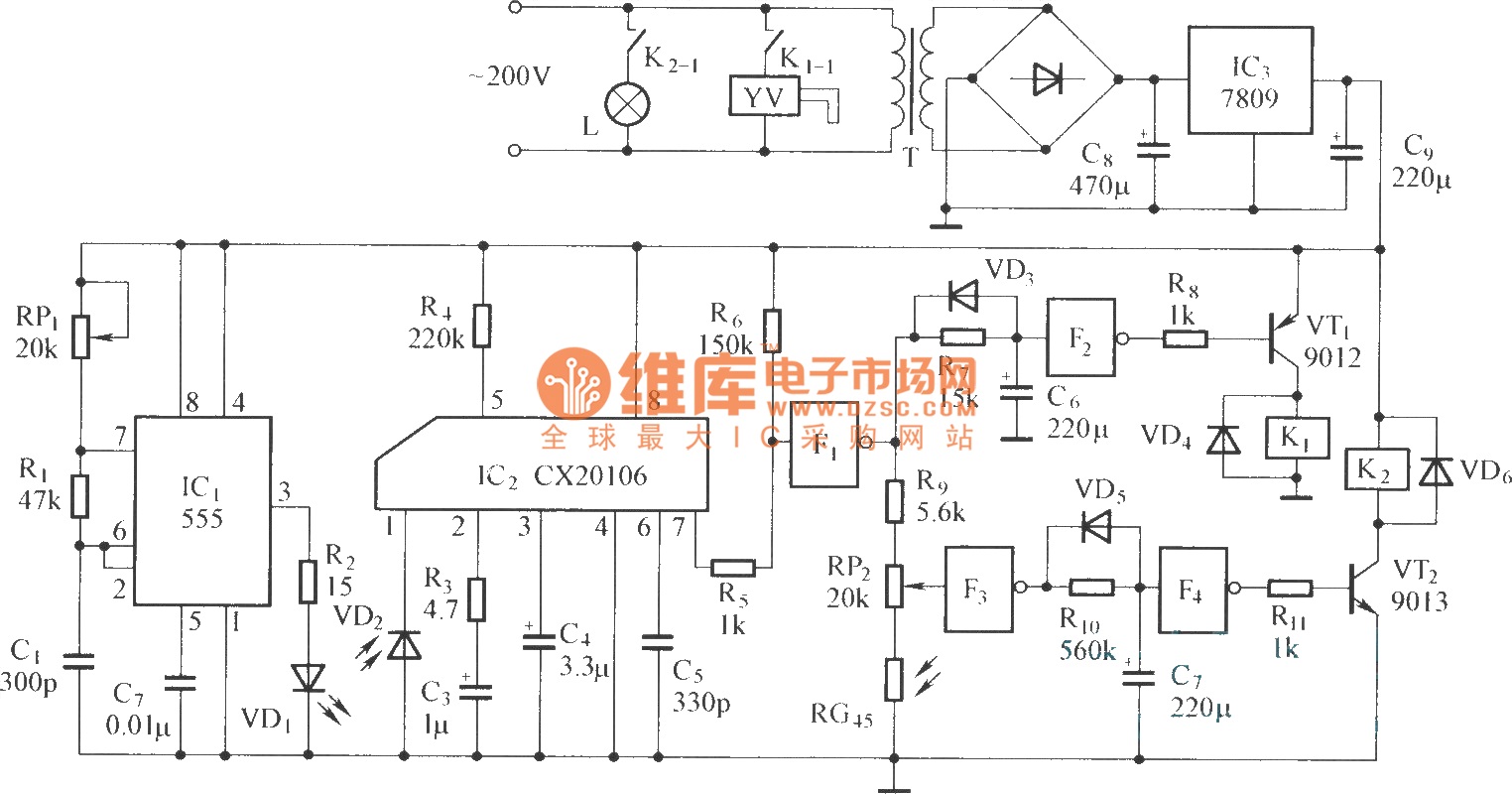
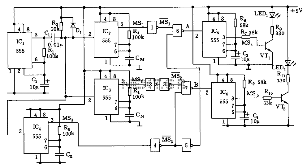
The circuit consists of the following components: (1) An infrared emitter which utilizes a multi-harmonic oscillator based on a 555 timer circuit. The oscillation frequency is determined by the values of RP1, R1, and C1, resulting in a frequency...
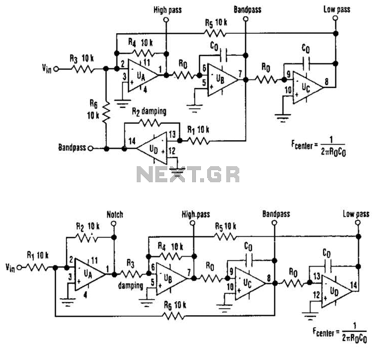
The classic state-variable (two-integrator) filter is well-known for its insensitivity to device parameter tolerances and its capability to provide three simultaneous separate outputs: high pass, bandpass, and low pass. These advantages often outweigh the requirement of a quad operational...