
Crystal Oscillator Circuit

Crystal oscillators are widely used in various applications, including timekeeping devices, communication systems, and signal processing. The fundamental operation of a crystal oscillator relies on the piezoelectric properties of quartz crystals, which resonate at specific frequencies when an alternating current is applied. The precision of the output frequency is a key advantage of crystal oscillators, making them ideal for applications where timing accuracy is critical.
The design of a crystal oscillator circuit typically involves selecting the appropriate crystal, which determines the oscillation frequency. The circuit usually includes an amplifier to sustain oscillation and feedback components to ensure stability. In the case of the CMOS inverter-based oscillator, the inverter provides the necessary gain, while the crystal sets the frequency of oscillation. The output can be further processed or divided down using counters or additional circuitry to meet specific application requirements.
When designing a PCB for a crystal oscillator, careful attention must be paid to the layout to minimize parasitic capacitance and inductance, which can adversely affect frequency stability and performance. Ground planes and short trace lengths are recommended to enhance signal integrity. Additionally, decoupling capacitors may be included near power supply pins to filter out noise.
In summary, crystal oscillator circuits are essential components in modern electronics, providing stable and accurate frequency sources for a wide range of applications. Proper design and implementation, including component selection and PCB layout, are crucial for achieving optimal performance.Crystal oscillator circuitis a simple oscillator circuit when we look at the schematic diagram. A crystal oscillator circuit is nothing but a replacement of an ordinary oscillator network, which is a combination of LC. This simplicity is also reflected in the number of physical components that are very compact, which occupy your printed circuit bo
ard. You live alone design the layout of components in such a way as to give the best results. Based on experience in designing a crystal oscillator, I can say very easily. If it is limited to a curiosity about how acrystal oscillator circuitis working, then the frequency counter is readable display a very stable frequency. Without having to make a PCB, simply by connecting the pin connections between the components involved.
However, for optimal results should be required data regarding the technical specifications of the crystal oscillator, and the components involved. You can just download the datasheet the crystal oscillator, and if necessary for the transistor or integrated circuit (IC) as well.
In addition, the layout of the components that also affect the quality of the output frequency. Here below are some of the crystal oscillator circuits for practical use. The following oscillator circuit using a crystal to produce 32. 768 KHz square wave output, and then fed to a 15 stage binary counter with 1 second square wave output. In the oscillator circuit diagram of the IC using a CMOS inverter 4069, to produce a better waveform, but a single transistor can be used.
As a note, if you do not want to buy a 32. 768 KHz crystal, can usually be found on a watch or computer mainboard that is damaged or not used anymore. EM7604, Low Power Crystal Oscillator 32. 768 KHz module can also be an option. EM7604 is an advanced low power CMOS circuit intended to be used together with a 32 768 kHz tuning fork crystal as a low-frequency clock oscillator.
Except the crystal, no other external components are required. The device combines excellent oscillator stability with very low power consumption. It is guaranteed over a very wide supply voltage and temperature range. In order to Achieve a high-frequency accuracy, the matched crystals should have a ± 20ppm tolerance or tighter. Crystal oscillator circuitwith the output frequency of 1 MHz as a base frequency of a signal generator using TTL SN7490 decade counter IC.
Basis of this frequency will be divided into several lower frequencies through a frequency divider 10 and 2. We aim to transmit more information by carrying articles. Please send us an E-mail to wanghuali@hqew. net within 15 days if we are involved in the problems of article content, copyright or other problems.
We will delete it soon. 🔗 External reference
Related Circuits
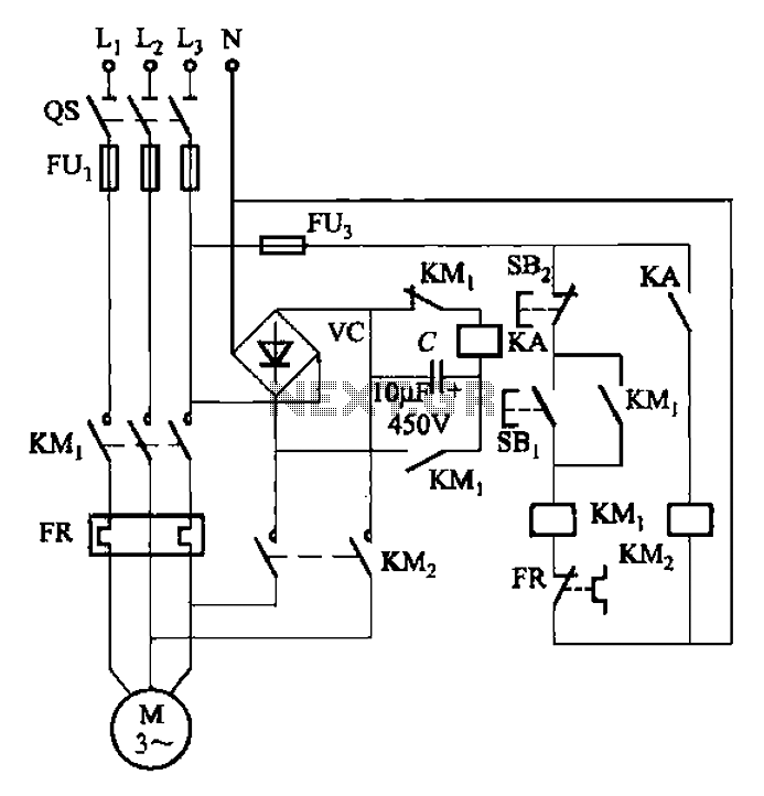
The circuit depicted in Figure 3-137 eliminates the need for a step-down transformer by utilizing the principle of energy storage capacitor discharge for braking. It can be employed to transform the power of motors with a rating of less...
Normally the base of a cordless phone has an adaptor and the handset has Ni-Cd cells for its operation. The base unit becomes inoperative in case of power failure. In such conditions, it is better to provide a backup...
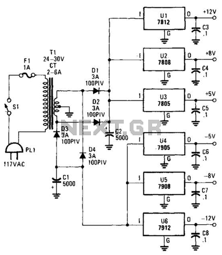
This dual-polarity, multivoltage power supply can be constructed with a minimal investment. The circuit utilizes 78XX and 79XX series voltage regulators, four 3-A diodes, a 24-30 V, 2-6 A transformer, and eight filter capacitors. The described dual-polarity, multivoltage power supply...
This site addresses a range of subjects pertaining to circuits and electronics. Some of the topics discussed on this site include: * Alternating Relay Switch * Photoswitch Relay. The site serves as a comprehensive resource for understanding various electronic components...
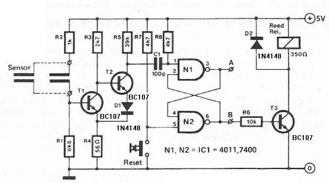
Humidity detector circuit electronic project using common electronic parts The humidity detector circuit is a project designed to measure and indicate the level of humidity in the environment. This circuit utilizes commonly available electronic components, making it accessible for hobbyists...
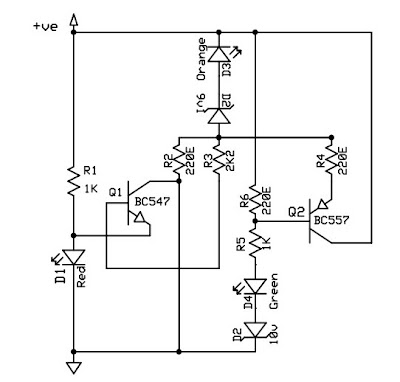
This circuit is a 12V battery checker that utilizes three LEDs to indicate different voltage levels. The red LED illuminates when the battery voltage is between 8V and 10V, the orange LED activates at voltages ranging from 10.5V to...