
Humidity detector circuit

The humidity detector circuit is a project designed to measure and indicate the level of humidity in the environment. This circuit utilizes commonly available electronic components, making it accessible for hobbyists and engineers alike. The fundamental operation of the circuit is based on a humidity sensor, which detects changes in humidity levels and converts these changes into an electrical signal.
The primary component of this circuit is a humidity sensor, such as the DHT11 or DHT22, which provides both humidity and temperature readings. The sensor typically outputs a digital signal that can be read by a microcontroller or microprocessor, such as an Arduino or Raspberry Pi, which processes the data accordingly.
Additional components in the circuit may include resistors, capacitors, and a power supply, which are used to stabilize the sensor's output and ensure reliable readings. An LED indicator can be incorporated to visually represent humidity levels, with different colors or blinking patterns indicating various humidity ranges.
For further enhancement, a display module, such as an LCD or OLED, can be integrated to provide a real-time readout of the humidity levels. This allows for easy monitoring and interpretation of the data. The circuit can also be designed to trigger alarms or notifications when humidity levels exceed predefined thresholds, making it suitable for applications in agriculture, HVAC systems, and environmental monitoring.
Overall, this humidity detector circuit serves as a practical example of how simple electronic components can be utilized to create effective measurement tools in various applications.Humidity detector circuit electronic project using common electronic parts 🔗 External reference
Related Circuits
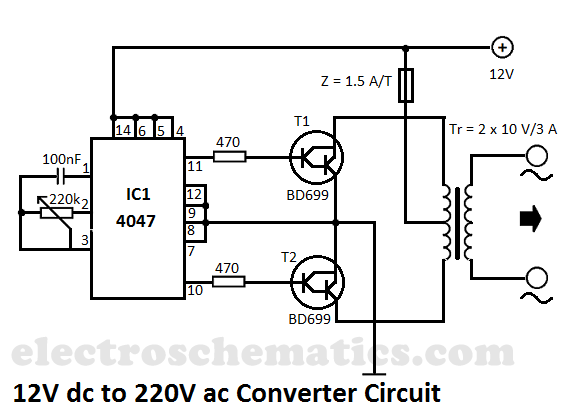
This DIY 12V to 220V voltage converter is built with the CMOS 4047, which serves as the main component of this compact voltage converter that transforms 12V DC into 220V AC. The 4047 is configured as an astable multivibrator,...
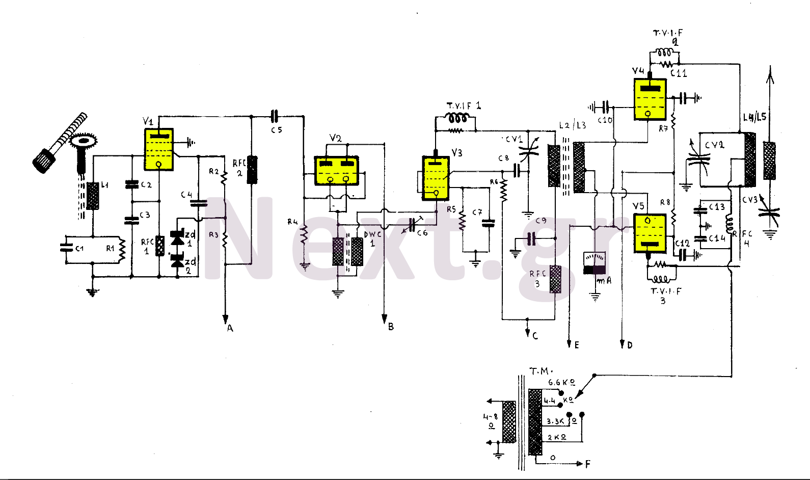
This 255W transmitter operates using coils designed for both medium and short waves. The antenna power is set at 255W and includes four operational states. The first state utilizes an EF80 tube functioning as a Colpitts Clapp oscillator. Frequency...

After being careful about every orientation of every transistor, a circuit board was designed around the LM387N, which was not the intended chip nor the one originally ordered (LM258, commonly referred to as LM358). During testing before adding larger...
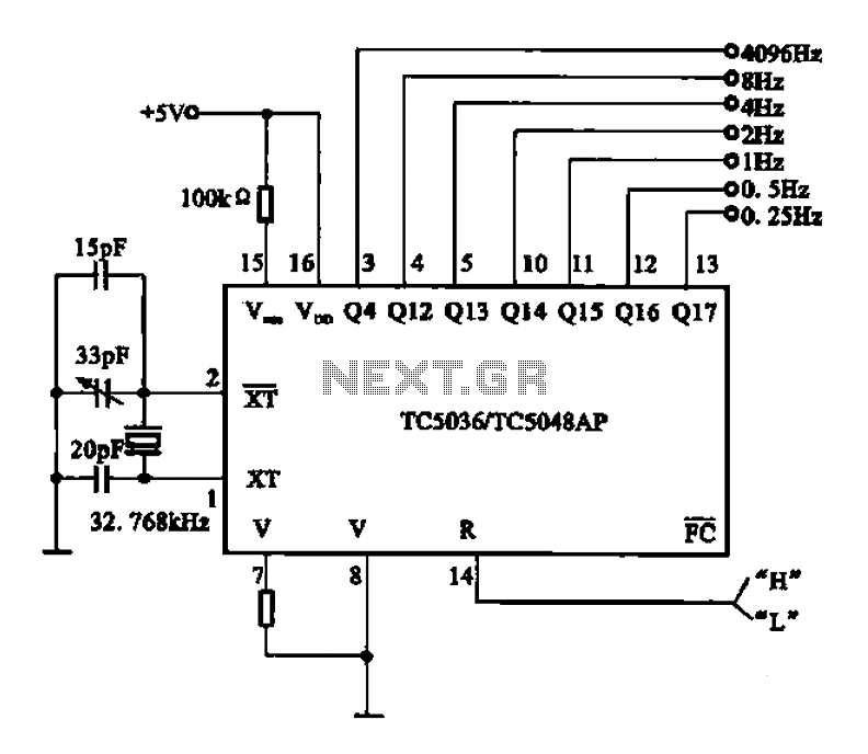
32.768 kHz; In MP3/MP4 devices, mobile phones, laptops, and other digital products, a real-time clock signal generating circuit is utilized, primarily composed of crystal resonators and TC5036/TC5048AP chip oscillators. This setup produces a raw 32.768 kHz crystal oscillator signal,...

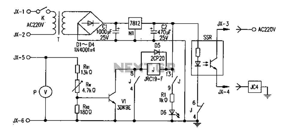
This is an AC-powered LED flasher that can drive two high-bright LEDs directly from the power obtained from the AC lines. The high-bright LED flasher can be... The AC-powered LED flasher circuit is designed to illuminate two high-bright LEDs using...
The FM302E-I-type FM transmitter exciter is utilized in Japan's NEC HPB a 1210 motherboard. It features direct carrier frequency modulation, phase-locked frequency stabilization, and frequency synthesis. The preamplifier (BLF-177 FET) is directly driven by an actuator, achieving a maximum...