
Crystal Oscillator with CMOS Inverter

The astable multivibrator circuit is designed to generate a continuous square wave output without requiring any external triggering. The CD4007 or MC14007 CMOS inverter provides the necessary logic levels to create the oscillation. This circuit configuration typically consists of two inverters connected in a feedback loop, where the output of the first inverter is fed into the second inverter.
The frequency of oscillation is primarily determined by the external resistors and capacitors connected to the circuit. The formula for calculating the frequency (f) can be expressed as:
f = 1 / (2 * (R1 + R2) * C)
where R1 and R2 are the resistances connected to the inverters, and C is the capacitance value of the timing capacitor. By adjusting these external components, the frequency can be varied, allowing for a wide range of applications, such as clock pulse generation, LED flashing, or tone generation in audio applications.
The circuit's power supply typically ranges from 3V to 15V, making it suitable for battery-operated devices. When implemented, the output can be taken from the second inverter, which provides a square wave signal. The high output impedance of the CMOS inverters allows for easy interfacing with other digital circuits, ensuring compatibility and versatility.
Overall, the astable multivibrator circuit using CMOS inverters is a fundamental building block in digital electronics, providing a reliable means of generating oscillatory signals for various applications.This is an astable multivibrator (oscillator) circuit using CMOS inverter. This circuit uses CD4007 or MC14007. This circuit has operating frequency range of.. 🔗 External reference
Related Circuits
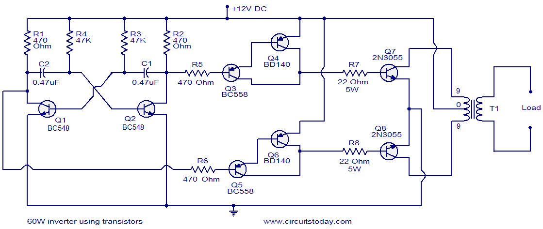
This circuit diagram illustrates a fully transistorized inverter capable of driving loads of up to 60W. Transistors Q1 and Q2 create a 50Hz astable multivibrator. The output from the collector of Q2 connects to the input of a Darlington...
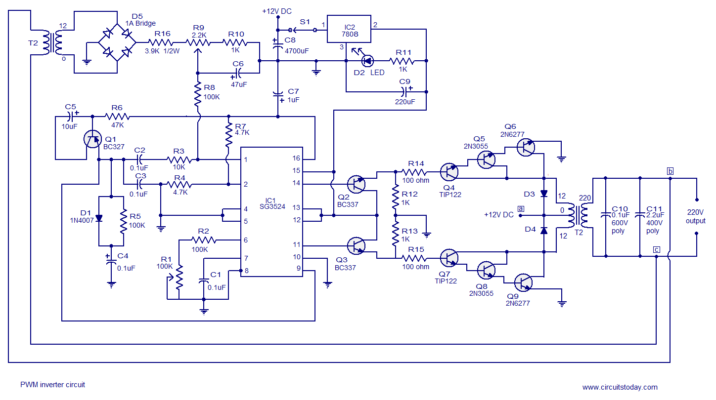
A simple PWM inverter circuit utilizes the SG3524 integrated circuit. This PWM inverter is designed for a 12V input, providing a 220V output with a maximum output power of 250 watts. The output power can be extended further. The described...
This 40W fluorescent lamp inverter enables the operation of 40W fluorescent tubes using any 12V source that can provide 3A. It is essentially a larger variant of the 12VDC Fluorescent Lamp Driver and can be utilized to illuminate both...
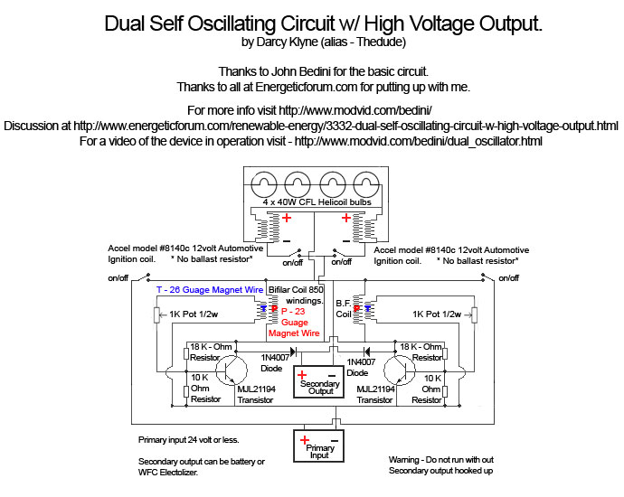
A Tesla pancake coil is connected in series with a bifilar wound coil to generate resonance and a sharp gradient discharge, which creates a vacuum flux. The circuit operates with a CFL at approximately 0.07 amps and 12.42 volts,...
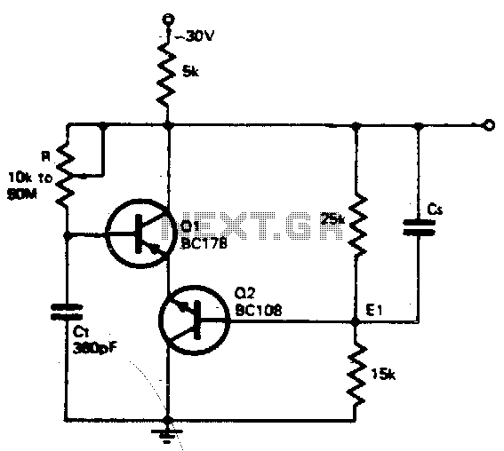
The timing resistor R can be adjusted to any value between 10 kΩ and 50 MΩ to achieve a frequency range from 400 kHz to 100 Hz. Connecting the timing resistor to the collector of Q1 ensures that Q1...
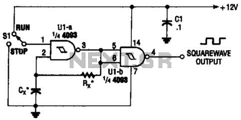
Two gates of the Quad 4093 are utilized to create an oscillator. The resistor (R) can range from approximately 5 kΩ to around 10 kΩ. The capacitor (Cx) can vary from about 10 pF to higher values, with the...