
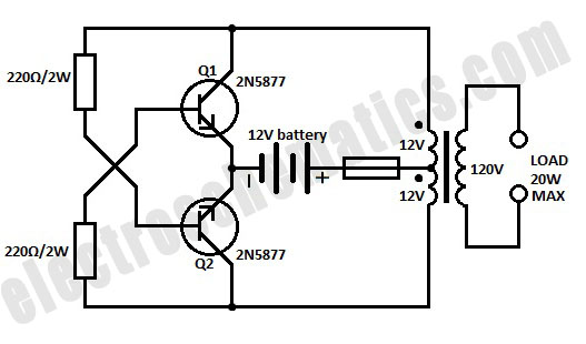
60W inverter using transistors

The described inverter circuit is designed to convert DC voltage into an AC voltage suitable for powering various loads. The core functionality is based on an astable multivibrator configuration, which generates a square wave output at a frequency of 50Hz. Transistors Q1 and Q2 operate in this configuration, where they alternately turn on and off, creating a continuous oscillation.
The output from Q2 is fed into the base of the Darlington pair consisting of Q3 and Q4. A Darlington pair is advantageous in this application as it provides high current gain, allowing for efficient switching of larger loads. Similarly, the output from Q1 drives the Darlington pair formed by Q5 and Q6, ensuring that both branches of the inverter can effectively drive the final output stage.
Transistors Q7 and Q8 are arranged in a push-pull configuration, which is critical for driving the output transformer. This configuration allows for the efficient transfer of energy to the transformer, maximizing the inverter's output power capability. The transformer then steps up or down the voltage as required for the load being powered.
In summary, this inverter circuit employs a combination of astable multivibrator and Darlington pairs to achieve a reliable and efficient AC output from a DC source, suitable for driving loads up to 60W. The use of transistors in a push-pull configuration enhances the performance and efficiency of the inverter, making it a practical solution for various applications.Here is the circuit diagram of a fully transistorized inverter that can drive up to 60W loads. Transistors Q1 and Q2 forms a 50Hz astable multivibrator. The output from the collector of Q2 is connected to the input of the Darlington pair formed by Q3 and Q4. Similarly the output of Q1 is coupled to the input of the pair Q5 and Q6. The output from t he Darlington pairs drive the final output transistors Q7 and Q8 which are wired in the push pull configuration to drive the output transformer. 🔗 External reference
Related Circuits
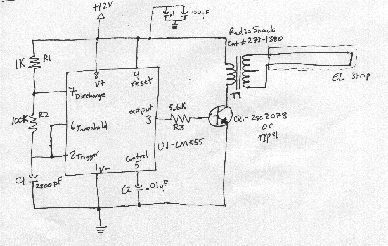
This document outlines a basic circuit designed to power high impedance, high voltage, low current devices such as electroluminescent (EL) backlights and fluorescent tubes. The project originated from the need for a simple yet flexible inverter circuit for an...
The double-ended working core square wave inverter transformer area product formula Bm represents the maximum magnetic flux. The primary side of the transformer features switches S1 and S2 in parallel with IRF32055. This parallel configuration is primarily due to...
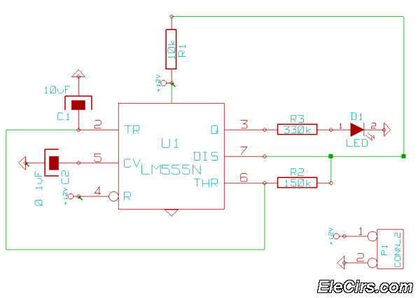
This is a very simple 555 timer circuit that serves as a straightforward theft deterrent, which may be just as effective. The idea is to have a flashing red LED indicate that your car is protected. This device can...
The device is designed to promote respectful time management during meetings, particularly useful in ship-room or SCRUM meetings. The following is a list of components required, including links for purchasing specific parts. It is advisable to check eBay or...
A simple 12-volt inverter circuit. This 120V AC power source is constructed using a basic 120V:24V center-tapped control transformer and four additional components. The circuit generates a clean 200-V peak-to-peak square wave at 60 Hz and is capable of...
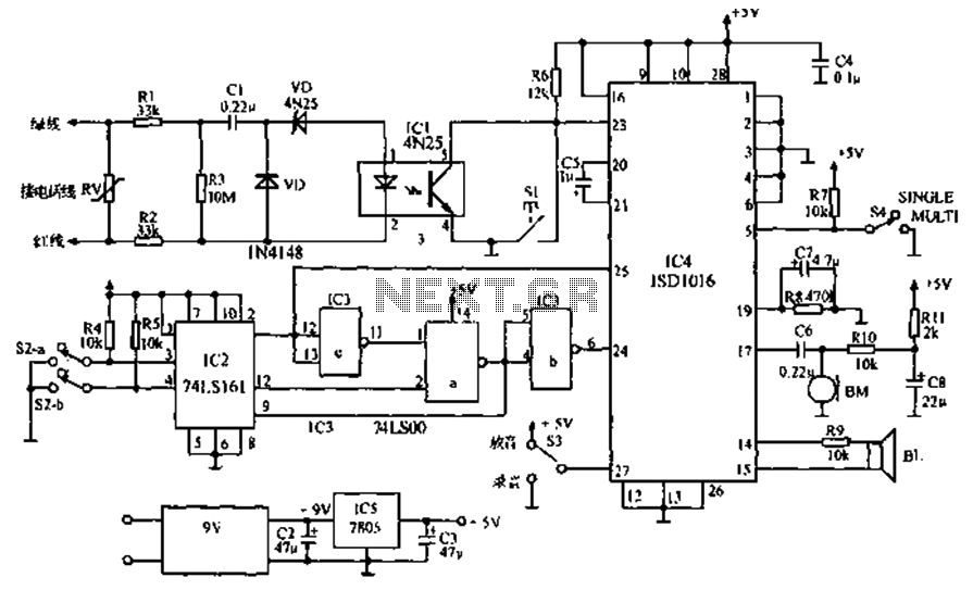
The call is made using the ISD1016 language chip for voice generation instead of a traditional phone ringing message controller schematic circuit. This controller can store messages, music, songs, or other sounds, serving as an alternative to monotonous ringing. The...