
Crystal Radio RF Amplifier

The circuit functions primarily as a regenerative amplifier, leveraging the unique characteristics of a transistor to achieve amplification and oscillation. The 500-ohm potentiometer plays a crucial role in adjusting the gain and controlling feedback, which is essential for maintaining stability while tuning into different stations. The connection points to the tuned circuit are critical; lower impedance taps provide a stable operating condition with reduced gain, while higher taps allow for greater amplification and potential oscillation, enhancing the circuit's ability to pick up weak signals.
The amplifier's design also incorporates a linear detector, which demodulates the radio frequency (RF) signals with improved fidelity compared to traditional regenerative circuits. This feature is particularly advantageous when the circuit is used in conjunction with audio amplifiers, as it ensures that the output sound quality remains clear and precise. The ability to adjust the regeneration level not only affects the gain but also influences the bandwidth of the received signals, allowing for a tailored listening experience based on the user's preferences.
In practical applications, the circuit can be enhanced by using longer antennas connected to taps, thereby improving reception quality. The use of a ferrite loopstick is recommended for environments with strong signals, as it can function effectively without an external antenna. However, careful adjustments to audio gain and regeneration settings are necessary to avoid distortion and ensure a balanced output. Overall, this amplifier circuit offers a versatile solution for radio enthusiasts seeking to improve their listening experience through effective gain control and signal processing techniques.The circuit below is a simple but effective amplifier which will give surprising performance improvement. This amplifier can exhibit negative resistance for low settings of the 500 ohm pot which results in extra gain or even oscillation.
So, the circuit can actually be considered to be a regenerative receiver with an external detector. The sensitivity is so high that no cold water pipe ground is needed and the antenna is short. The behavior of the amplifier depends on how it is connected to the tuned circuit. When connected to a lower impedance tap as shown in the schematic, the gain will be lower with less tendency to oscillate. Higher taps or even connection directly to the antenna will give higher gain and even oscillation. The 500 ohm pot is adjusted to give adequate gain without squealing as stations are tuned. High regeneration settings will actually narrow the bandwidth of the tank enough to give the sound a "mellow" quality which sounds pretty good in a "tinny" crystal earphone!
Lower settings are best when using an audio amplifier and the fidelity is quite good thanks to the linear detector (typical regens use changes in the operating point of the transistor to demodulate the RF). As with any regen, the gain may be increased after the station is tuned in and the circuit will oscillate, locked to the station`s frequency.
Longer antennas should be connected to taps instead of across the whole coil. A ferrite loopstick will pick up stronger stations with no antenna at all but use more audio gain after the diode detector and reduce the regeneration to get adequate bandwidth or the sound will be muffled. Be the first of your friends to get free diy electronics projects, circuits diagrams, hacks, mods, gadgets & gizmo automatically each time we publish.
Your email address & privacy are safe with us ! 🔗 External reference
Related Circuits
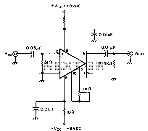
This circuit provides approximately 20 dB of voltage gain with a frequency range from 0.5 to 50 MHz. The low-frequency response of this circuit can be extended by increasing the value of the 0.05 µF capacitor or by removing...
This is a design for a low noise microphone preamplifier, which is ideally suited to low impedance (600 Ohm nominal) microphones. One limitation is that it is not balanced, which is not a problem in a home recording environment,...
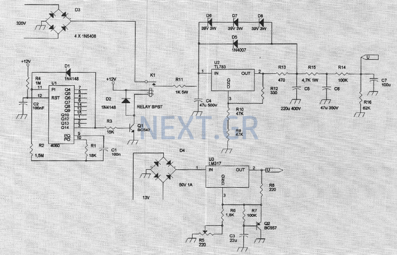
The amplifier feeding the final amplification stage operates with unstabilized voltage. The output stage, utilizing push-pull operation, exhibits significant rejection of the supply voltage. However, the earlier stages do not provide the same level of rejection, resulting in unwanted...
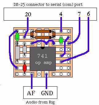
It's a very easy interface to build and requires only a few £/$ worth of components. As you can see by the picture on the right, there's not much to it. To be honest, the picture is misleading. This...
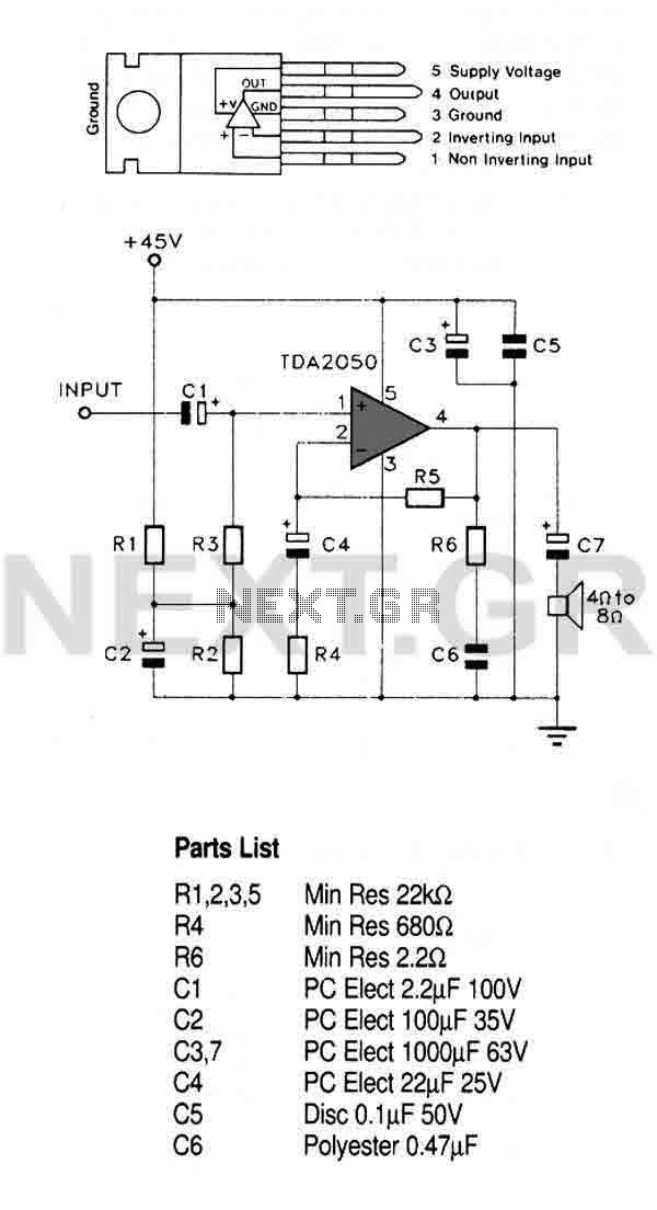
This circuit utilizes a high-quality audio amplifier integrated circuit (IC) housed in a 5-pin TO220 package, which eliminates the need for insulating washers between the metal tab and heatsink in single rail supply applications. The amplifier is capable of...
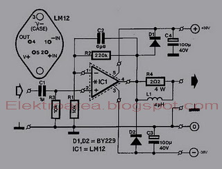
This is an 80W power amplifier OCL circuit that utilizes the integrated circuit LM12. It effectively enhances bass and treble performance. When connected to a CD player, it produces high-quality sound, especially when paired with a good pre-tone control....