
Ham radio Communication

The described interface is a versatile communication tool designed for amateur radio enthusiasts, particularly those interested in digital modes. The primary function of this interface is to facilitate both receiving (RX) and transmitting (TX) capabilities, enhancing its utility beyond the original hamcomm interface, which was limited to RX only.
The interface typically consists of a microcontroller or a simple logic circuit that translates audio signals from the radio into digital data that can be processed by a computer and vice versa. The components required for building this interface are minimal and cost-effective, often including resistors, capacitors, diodes, and a few integrated circuits.
In operation, the interface connects to the audio output of the radio for receiving signals and to the audio input for transmitting. This allows users to decode various digital modes such as RTTY (Radio Teletype), AmTOR (Amateur Teleprinting Over Radio), and SSTV (Slow Scan Television), which are widely used in amateur radio for data transmission. The interface can also be adapted for use in fax systems and packet radio communications, making it a flexible solution for data transmission in various formats.
To construct this interface, attention must be paid to the signal levels and impedance matching between the radio and the interface to ensure optimal performance. Proper grounding and shielding techniques should also be employed to minimize noise and interference, which can significantly affect digital communication quality.
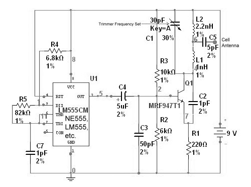
Overall, this hamcomm interface is an excellent project for those interested in exploring digital modes in amateur radio, providing both a practical application and an opportunity to learn about digital signal processing and interfacing techniques.Its a very easy interface to build an requires only a few £/$ worth of components. A you can see by the picture on the right, there`s not much to it. To be honest, the pictur is misleading. This hamcomm interface has an added `extra` facility. The original hamcom interface was RX (receive) only. This one has a TX (transmit) bit added on so that th user can send also. So what can you do with it? Pretty muc anything really. Its most commonly used for the reception of data modes like RTTY an AmTOR but can be found on simple Fax systems and of course SSTV systems. I have even see it used to decode 1200bd packet radio. Its 🔗 External reference
Related Circuits
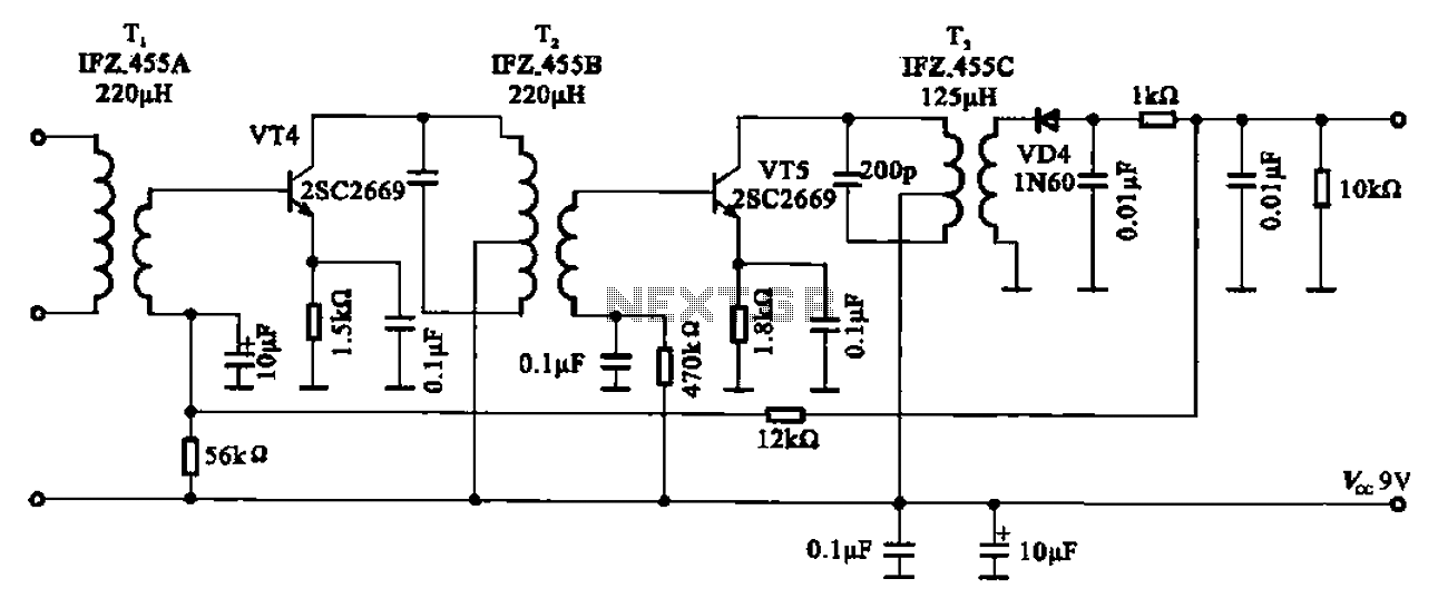
AM radio shows the IF amplifier and detector circuit. The mixer receives the intermediate frequency output signal from the transformer after the device. This signal is applied to the base of the intermediate frequency transistor VT4. The collector load...
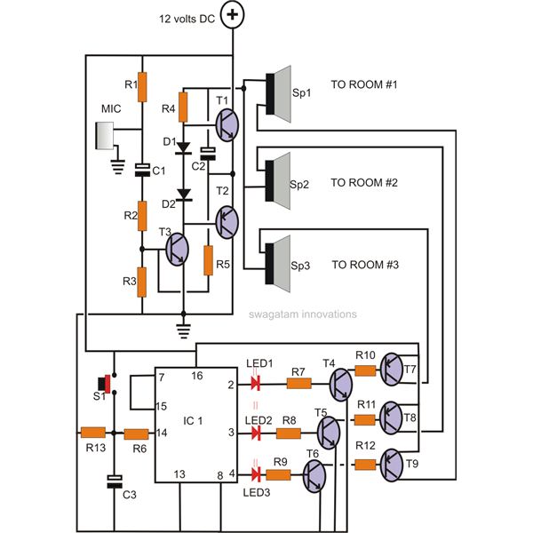
A home intercom system can be constructed using a versatile circuit design. This system allows communication across up to ten different locations or rooms discreetly. It utilizes a single changeover switch for selecting the desired location, replacing the traditional...
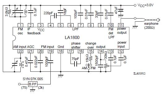
This portable AM/FM radio circuit is designed using the LA1800 integrated circuit (IC) along with several external components. The circuit diagram illustrates that the LA1800, manufactured by Sanyo Semiconductors, requires only a few additional components. The output signal is...
Superheterodyne receivers have been mass-produced since around 1924, but for reasons of cost did not become successful until the 1930s. Superheterodyne receivers represent a pivotal advancement in radio technology, characterized by their ability to convert high-frequency signals into lower...
This project originates from the past and has demonstrated significant success. It serves as the foundation for an 8-channel proportional R/C (AM) and 145MHz FM chat box. The receiver design is straightforward and includes a single transistor mixer followed...
This device functions as a reversal of a radio station, sending a null signal to a selected frequency to eliminate the actual broadcast. The radio transmitter operates at a loss of 10,000W; therefore, this circuit is intended for use...