
Crystal Radio with LM358N

Antenna: 10 mt of electrical wire, WELL insulated from ground. This must be the arrangement: wall |...O...O...O----------------------------------O...O...O...| wall.
Inductor: Wind 60 windings of enamel copper wire onto a 2-inch ferrite core (1 cm diameter or a bit less).
RF GROUND: Like for Tesla coils, it must be a good ground; otherwise, the signal will be poor. Place a metal nail and connect to the circuit with alligator clips.
C1: It would be difficult to make it reliable; in addition, it needs a capacitance meter. It is better to buy it or find it in old broken radios. If building, use the parallel plate capacitance formula and make two carton disks (10 cm diameter with an aluminum foil semi-disk each) separated through paper. Place a nail in the center (make sure not to short the capacitor) and connect it with small wires. Rotating a disk with respect to the other will change the shared surface and increase capacitance, but this is not reliable because as soon as you approach it, you will detune it. It is better to use a commercial variable capacitor with an insulated lever.
C2: Use paper, aluminum foil, or LDPE.
Diode: Buy it; it is not advisable to look for lead sulfide crystals.
High impedance headphones: Difficult to find; the only substitute is an amplifier.
Amplifier + low impedance headphones: Use a general-purpose op-amp with feedback resistors and a low impedance headphone (such as those from cassette or CD players), but power is needed.
The described circuit constitutes a basic AM radio receiver utilizing simple components and principles. The antenna, a 10-meter long insulated wire, captures the radio frequency (RF) signals from the air. The RF signals are then fed into a tuned circuit formed by the inductor and capacitor, which resonates at the desired frequency. The inductor is constructed by winding 60 turns of enamel-coated copper wire around a ferrite core, optimizing the inductance for the tuning process.
The variable capacitor (C1) is crucial for adjusting the resonant frequency of the circuit to match the frequency of the desired AM station. While constructing a homemade capacitor is possible, purchasing a commercial variable capacitor is recommended for reliability and ease of use. This capacitor allows fine-tuning of the circuit, which is essential for effective signal reception.
Once the signal is tuned, it is rectified by a diode, which converts the AC signal into a DC signal. The smoothing capacitor (C2) then filters out any remaining AC ripple, providing a more stable audio signal to the headphones. The choice of capacitor material for C2 can vary, but it should be capable of handling the necessary voltage and capacitance requirements.
The output stage of the circuit involves high impedance headphones, which are sensitive enough to convert the small audio signal produced by the rectification process into audible sound. If high impedance headphones are unavailable, using a low impedance headphone with an operational amplifier (op-amp) can amplify the signal sufficiently for listening.
For optimal performance, a good RF ground connection is essential. This can be achieved by driving a metal nail into the ground and connecting it to the circuit with alligator clips, ensuring a solid ground reference for the RF signals.
Overall, this circuit exemplifies a straightforward approach to building an AM radio receiver using readily available materials, demonstrating fundamental principles of electronics and radio communication.The AM signal is captured by the antenna , 10 mt long horizontal wire, WELL insulated from earth (I mean distant, to lower the stray capacitance coupling with ground which will adsorb some signal ). The Inductor and capacitor forms a resonator, that will tune with the station which frequency is F= 1/ (2*pi*sqrt(L*C)), so adjust C1 for tuning.
The signal is rectified (demodulated) and smoothed by C2. The high impedance headphones has fine internal wiring and lots of windings, so even a small current will produce an audio output. Antenna: 10 mt of electrical wire, WELL insulated from ground (use plastic bottle caps and hoowup wire to keep it high). This must be the arrangement |=wall ..=hookup wire o=plastic cap --=wire antenna : | 10 mt | wall |...O...O...O----------------------------------O...O...O...| wall | | | to receiver Inductor: wind 60 windings of enamel copper wire onto a 2 inch ferrite core (1 cm diameter or a bit less) RF GROUND: Like for tesla coils, it must be a good ground, otherwire the signal will be poor.
Place a metal nail and connect to the circuit with alligator clips. C1: It would be difficult to make it reliable, in addition needs a capacitance meter, better buing it or finding it in old broken radios. But if you want to build it use the parallel plate capacitance formula and make two carton disks (10 cm diameter with a alu foil semi disk each separated through paper, place a nail in center (make sure to not short the capacitor) and connect it with small wires, rotating a disk respect to the other will change shared surface and increase capacitance, but how i said this is not reliable because as soon ase you approach it, you will detune it.
So better use a commercial variable cap with insulated lever. C2: use paper, alu foil or ldpe (but i don't think that you will be interested in a 10KV capacitor so use thin LDPE) Diode: Buy it. I don't advice you looking for Lead Sulphyde cristals.... High impedance headphones: Difficult to find , the only substitute is an amplifier (see below) Amplifier + low impedance headphones: Use a general purpose opamp with feedback resistors and a low impedance headphone (as these of cassette, cd players), but you need power...
:-( It is very nice to build, hearing a sound of a radio station without power is very fun. I reconstrected it basing on my fathers rememberings and very old texts, improved a bit with some physics. Constructing from almost anything is possible , even the headphone, as many cristal radios have been found in nazis prison camps build by prisoners from very limited resources (as everything in a prison camp) and some in foxholes (called foxhole radios).
🔗 External reference
Related Circuits
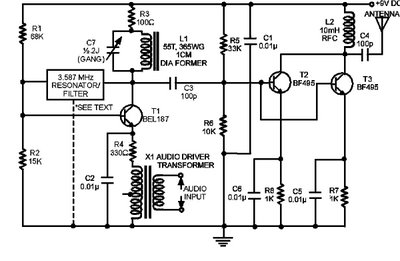
The circuit presented here is a powerful AM transmitter utilizing a ceramic resonator/filter operating at 3.587 MHz. This circuit primarily relies on a transistor for its core functionality. It is possible to use resonators/filters of other frequencies, such as...
Op-amps have been widely used in low-frequency oscillators. Op-amps, or operational amplifiers, are versatile components frequently utilized in the design of low-frequency oscillators. These devices are capable of generating periodic waveforms, such as sine, square, or triangular waves, which are...
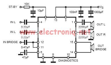
In practical applications, a series resistance must always be included. This component serves the dual purpose of limiting the current at pin 7 and smoothing the ON/OFF transitions during standby. In electronic circuits, particularly those involving integrated circuits (ICs) or...
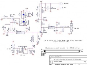
This FM 88-108 MHz radio amplifier is equipped with a BLF 245 and can be used with a heatsink from a processor and a cooler. The BLF 245 datasheet can be downloaded. The FM 88-108 MHz radio amplifier utilizing the...
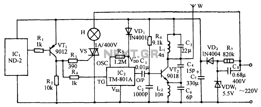
The circuit includes a comprehensive array of components such as vibration sensors, a follower, a lamp relay control circuit, a voice sounding circuit, a high-frequency oscillation circuit, and an AC rectifier buck power supply circuit. The vibration sensor is...
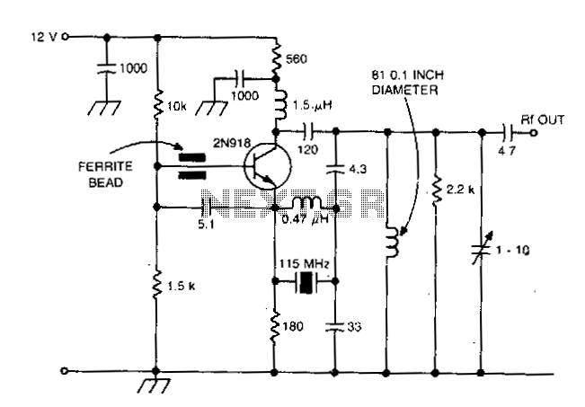
This design is intended for high reliability across a broad temperature range utilizing fifth and seventh overtone crystals. The inductor connected in parallel with the crystal induces antiresonance of crystal capacitance (Co) to reduce loading effects. This technique is...