
Overtone crystal oscillator

The circuit employs overtone crystals, which are known for their ability to operate at higher frequencies than fundamental mode crystals. The selection of fifth and seventh overtone crystals allows for precise frequency stability and performance in demanding environments. The use of these overtone modes significantly enhances the frequency response and minimizes phase noise, making them suitable for applications that require stringent timing requirements.
In this design, the inductor is strategically placed in parallel with the overtone crystal to create a resonant circuit that effectively counters the loading capacitance presented by the crystal. This configuration leads to an antiresonant condition, which optimizes the circuit's performance by ensuring that the effective load on the crystal is minimized. This is crucial as excessive loading can dampen the oscillation amplitude and degrade the frequency stability, particularly in high-temperature or varying environmental conditions.
The choice of components in this circuit must be made with care to ensure that they can withstand the specified temperature range while maintaining the desired electrical characteristics. High-quality inductors and overtone crystals should be selected to guarantee the reliability of the circuit operation over time.
This design is particularly advantageous for applications in telecommunications, precision timing devices, and other electronic systems where frequency stability is paramount. By utilizing overtone crystals in conjunction with a parallel inductor, this circuit achieves an optimal balance of performance, reliability, and thermal stability.This design is for high reliability over a wide temperature range using fifth and seventh overtone crystals. The inductor in parallel with the crystal causes antiresonance of crystal Co to minimize loading This technique is commonly used with overtone crystals.
Related Circuits
On following pages circuits are shown for 3rd overtone crystals 15 to 65MHz and 5th overtone crystals 60 to 105 MHz operating in their series resonant mode. In both of these circuits with the crystal short circuited, the oscillator...
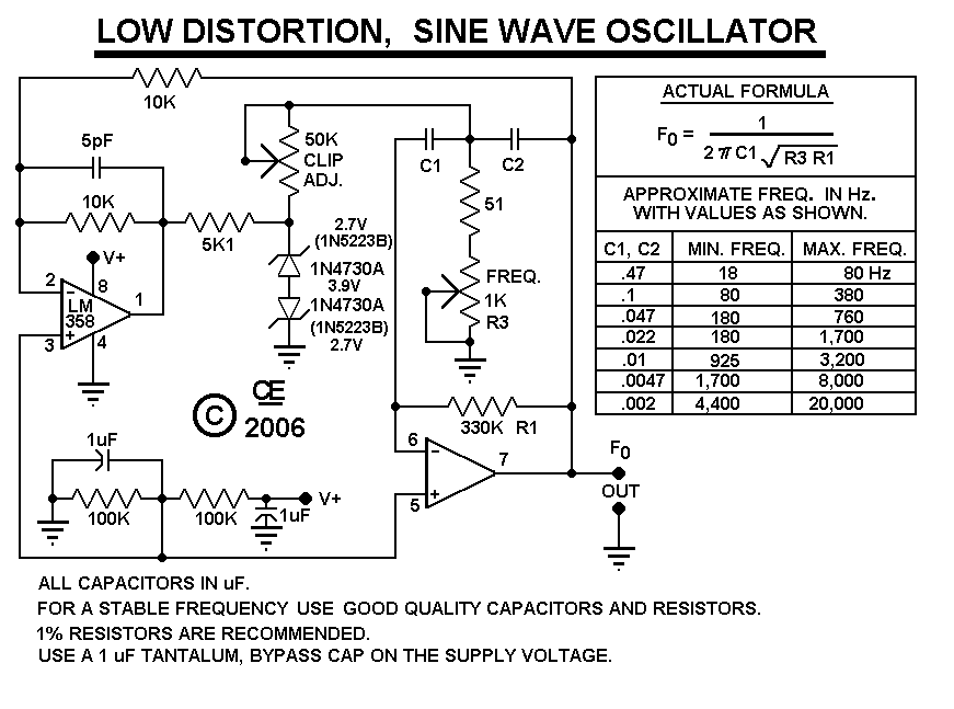
After constructing the device, adjust the frequency to the desired level using the "Frequency Control." Then, utilize an oscilloscope to fine-tune the waveform for optimal performance with the "Clip Control." The sharp rise and fall times of square waves...
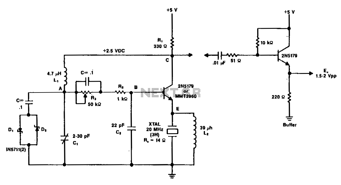
A typical circuit operating at 20 MHz is illustrated. The crystal, featuring an internal series resistance (Rs) of 14 ohms, oscillates at its third harmonic frequency. Diode clamps D1 and D2 ensure constant amplitude control. The transistor functions continuously...
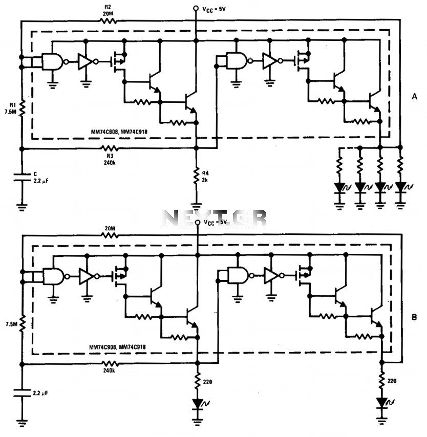
The driver in the package is configured as a Schmitt trigger oscillator (A), utilizing resistors R1 and R2 to create hysteresis. The inverting feedback timing components consist of resistor R3 and capacitor C, while resistor R4 serves as the...

This circuit is guaranteed to oscillate at a frequency of approximately 2.2/(R1 x C) if R2 is greater than R1. Additionally, the number of gates can be reduced further by replacing gates 1 and 2 with a non-inverting gate. The...
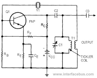
This circuit represents a variant of an Armstrong Oscillator. This specific example incorporates a crystal along with the LC tank circuit utilized in the previous Series-Fed Armstrong Oscillator. By definition, the Armstrong Oscillator employs a tickler coil for feedback...