
Crystal tester

The oscillator circuit utilizes the 2N3563 transistors in a feedback configuration to generate oscillations. When a compatible crystal is connected to the test clips, it establishes the necessary conditions for oscillation, allowing the circuit to produce a stable frequency signal. The output from the oscillator is directed to two 1N4148 diodes arranged in a rectifier configuration, which convert the AC signal from the oscillator into a DC voltage. This rectified voltage is then smoothed by the capacitor C1, which serves to filter out any remaining AC ripple, providing a clean DC voltage level.
The positive voltage across capacitor C1 is critical as it controls the operation of the second transistor Q2. When this voltage exceeds a certain threshold, Q2 turns on, allowing current to flow through LED1. The LED serves as an indicator, visually confirming the operational status of the crystal. If the LED is illuminated, it indicates that the crystal is functional and oscillating properly, while a non-illuminated LED suggests that the crystal may be defective or not connected.
Powering the circuit with a nine-volt battery ensures that it has sufficient voltage for operation while maintaining a compact form factor suitable for portable applications. The inclusion of an SPST pushbutton switch allows for easy control of the circuit, enabling users to conserve battery life by disconnecting power when the circuit is not in use. This design consideration is essential for maintaining the longevity of the battery, particularly in applications where the circuit may not be used continuously. Overall, this oscillator circuit is a practical tool for testing crystal functionality in electronic applications.Transistor Ql, a 2N3563, and its associated components form an oscillator circuit that will oscillate if, and only if, a good crystal is connected to the test clips. The output from the oscillator is then rectified by the two 1N4148 diodes and filtered by CI, a,01 µ capacitor.
The positive voltage developed across the capacitor is applied to the base of Q2, another 2N3563, causing it to conduct. When that happens, current flows through LED1, causing it to glow. Since only a good crystal will oscillate, a glowing LED indicates that the crystal is indeed OK. The circuit is powered by a standard nine-volt transistorj*adio battery and the SPST pushbutton power-switch is included to prolong battery life.
Related Circuits
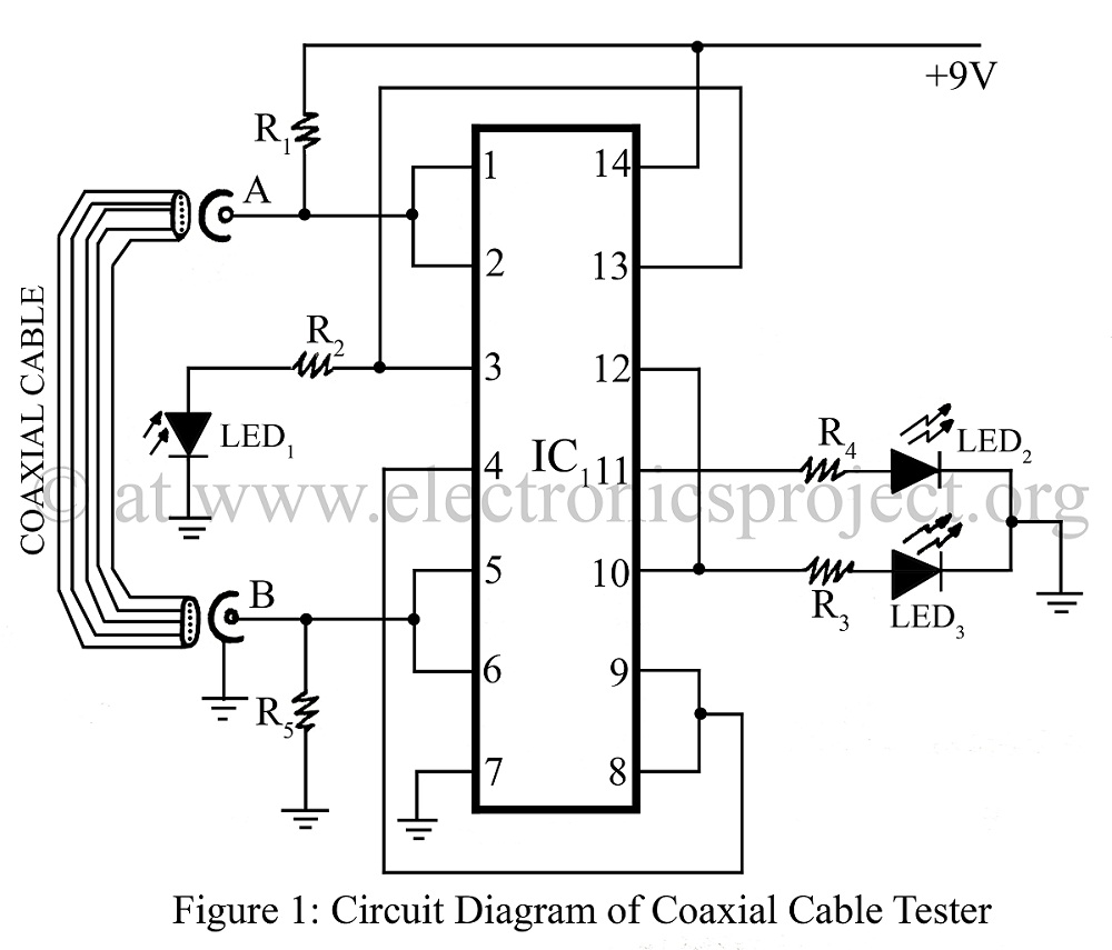
A coaxial cable tester is utilized to determine the condition of a coaxial cable, identifying whether it is open, short-circuited, or functioning correctly. This device employs a digital IC 4001 and includes a circuit description along with a parts...
This circuit utilizes a single 555 Timer IC along with a small transformer to generate high voltage for testing zener diodes with voltage ratings up to 50VDC. The 555 timer operates in astable mode, with the output from pin...
Here is a simple radio that is easy to build and inexpensive. In fact, you probably have all the parts you need in your junk box. You'll be surprised at the great reception with this little set. More: The...
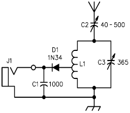
A crystal radio receiver is a very simple radio receiver that requires no battery or external power source, operating solely on the energy harvested from radio waves through a long antenna. A crystal radio receiver is a passive radio receiver...

This circuit is a 2 MHz crystal oscillator utilizing a CMOS transistor pair. It is particularly suitable for applications in digital watches and clocks due to its low power consumption. The oscillator is constructed by connecting a CMOS transistor...
.jpg)
Integrated circuits (ICs) with on-board oscillators that require low-frequency fundamental crystals are common; however, IC frequency multipliers now require the higher frequencies provided by third overtone crystals. The third-overtone (3OT) crystal oscillator is more complex than its fundamental counterpart,...