
Crystal Testers

The circuit utilizes a frequency counter and a microcontroller to measure the oscillation frequency of the quartz resonator under test. The resonator is connected to an oscillator circuit, which generates a signal that is then processed by the microcontroller. The microcontroller compares the measured frequency against predefined thresholds to determine the operational status of the resonator.
The LED indicator is connected to a GPIO pin of the microcontroller, which turns on when the resonator is functioning correctly, providing a visual confirmation. Additionally, an audio output, typically a piezo buzzer, is included in the design to provide an audible confirmation of the resonator's status.
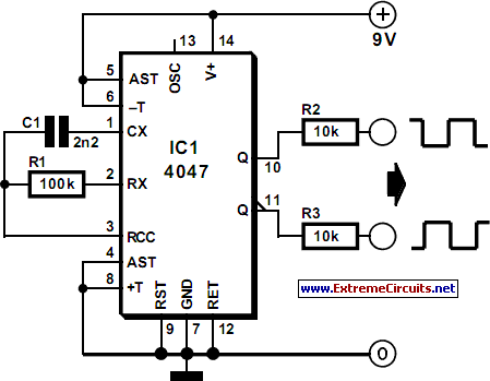
The switch S2 is a multi-position toggle switch that allows the user to select between different frequency ranges, enhancing the versatility of the circuit. Each position of the switch corresponds to a specific range, which the microcontroller is programmed to recognize, adjusting its measurement parameters accordingly.
To ensure accurate measurements, the circuit may also include bypass capacitors and filtering components to eliminate noise and stabilize the power supply. Proper grounding techniques should be applied to minimize interference, particularly in high-frequency applications.
Overall, this circuit serves as a practical tool for testing and verifying the functionality of quartz resonators, making it valuable for applications in electronics testing and development.This circuit enables you to test quartz resonators at the range values from 32kHz to 24MHz. Confirmation of good state of quartz resonator is done by diode signalling LED and acoustic signal. Switch S2 enables change of range. 🔗 External reference
Related Circuits
Liquid-crystal displays (LCDs) are available in various sizes and configurations, including their pinouts. Many of these displays require the manufacturer's documentation for proper usage, which is often difficult to locate when needed. Consequently, a small tester designed to identify...
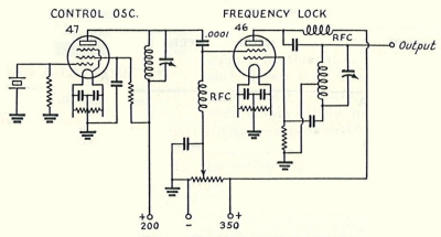
A classic amateur radio transmitter topology, known as the oscillator-amplifier (often referred to as master oscillator, power amplifier, or MOPA), utilizes one tube for frequency control and another for RF power amplification. In its quartz-crystal-controlled form, it typically allows...
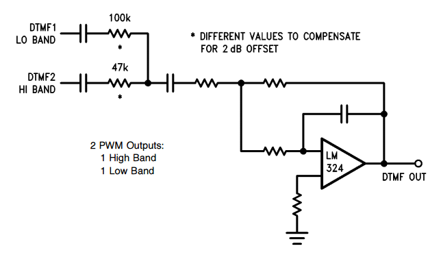
DTMF (Dual Tone Multiple Frequency) is associated with digital telephony, and provides two selected output frequencies (one high band, one low band) for a duration of 100 ms. DTMF generation consists of selecting and combining two audio tone frequencies...
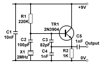
In applications where good frequency stability is essential, such as radio transmitters, basic LC oscillators may not maintain their frequency without drifting. This drift can be caused by small changes in supply voltage, although stabilized power supplies can help...
The world is full of xtal oscillators twiddled by digital designers lacking in the analog design knowledge necessary. Just look at all the PC real time clocks that lags or leads by several minutes per day. And they eat...

The Precision VXO (PVXO) and its corresponding Crystal Test Fixture (CTF) were developed to offer an economical method for evaluating the characteristics of crystals and measuring their series resonant frequency. This information enables the construction of low-cost, high-performance crystal...