
Crystal Oscillator II

Crystal oscillators, or xtal oscillators, are essential components in various electronic devices, providing stable frequency references for timing and synchronization. However, the design and implementation of these oscillators require a solid understanding of both analog and digital principles to ensure accurate performance. Many digital designers may overlook critical analog design considerations, leading to issues such as drift in real-time clocks (RTCs), which can result in timekeeping errors of several minutes per day.
A typical crystal oscillator circuit consists of a quartz crystal, an amplifier, and feedback components. The crystal acts as a resonator, vibrating at a specific frequency when an alternating current is applied. The amplifier, often implemented using operational amplifiers or dedicated oscillator ICs, provides the necessary gain to sustain oscillation. Feedback components, including resistors and capacitors, are crucial for setting the oscillation frequency and ensuring stability.
In many cases, integrated circuits (ICs) designed for digital applications may include pins labeled "Xtal here" for connecting external crystals. However, these connections can be misleading if the ICs are not designed with adequate analog circuitry to support the crystal's characteristics. Without proper impedance matching and load capacitance considerations, the oscillator may not operate at its intended frequency, leading to unreliable timekeeping.
To mitigate these issues, designers should prioritize understanding the specifications of the crystal, including its series and parallel resonance frequencies, load capacitance requirements, and drive level ratings. Additionally, implementing proper decoupling techniques and ensuring a stable power supply can significantly enhance the performance of crystal oscillators. Careful layout practices in PCB design, such as minimizing trace lengths and avoiding interference from digital signals, are also essential for maintaining oscillator stability.
In conclusion, while xtal oscillators are vital for accurate timing in digital systems, their design requires a comprehensive understanding of analog principles. By addressing these considerations, designers can create more reliable and accurate timekeeping solutions that do not suffer from the common pitfalls associated with poor oscillator design.The world is full of xtal oscillators twiddled by digital designers lacking in the analog design knowledge necessary. Just look at all the PC real time clocks that lags or leads by several minutes per day. And they eat backup batteries too! IC`s with pins that say "Xtal here" can`t be trusted either! 🔗 External reference
Related Circuits
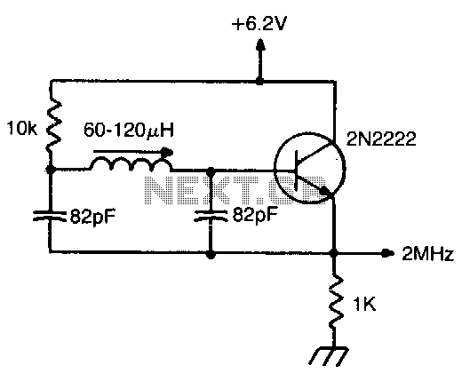
Miller 9055 miniature slug-tuned coil; all resistors 1/4W 5%; all capacitors minimum 25 V ceramic. The Miller 9055 miniature slug-tuned coil is designed for applications requiring precise tuning and compact form factors. This coil is characterized by its miniature size,...
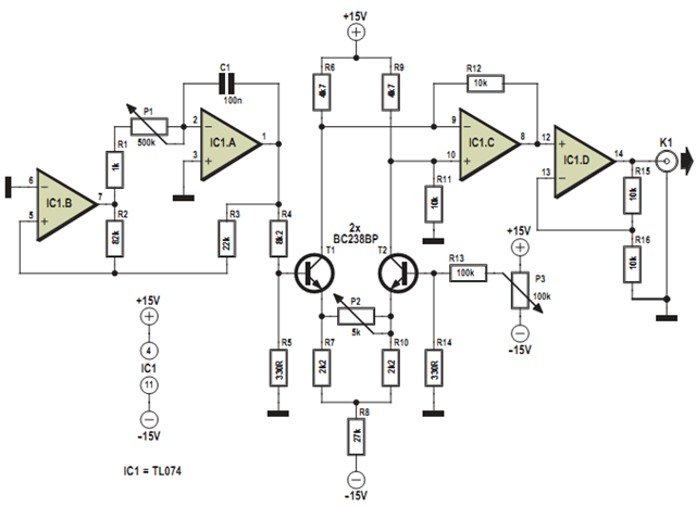
This design was developed to partially replace the well-known 8038 chip, which is no longer in production and therefore difficult to obtain. An existing design for driving a Linear Variable Differential Transformer (LVDT) sensor utilized the 8038 as a...
On following pages circuits are shown for 3rd overtone crystals 15 to 65MHz and 5th overtone crystals 60 to 105 MHz operating in their series resonant mode. In both of these circuits with the crystal short circuited, the oscillator...
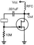
A Pierce Oscillator is a type of oscillator that utilizes a crystal instead of a parallel-resonant circuit (LC circuit). This oscillator also employs the voltage developed from a tap between two capacitors in the tank circuit. Both Pierce Oscillators...
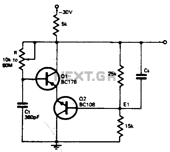
The timing resistor R can be adjusted to any value between 10 kΩ and 50 MΩ to achieve a frequency range from 400 kHz to 100 Hz. Connecting the timing resistor to the collector of Q1 ensures that Q1...
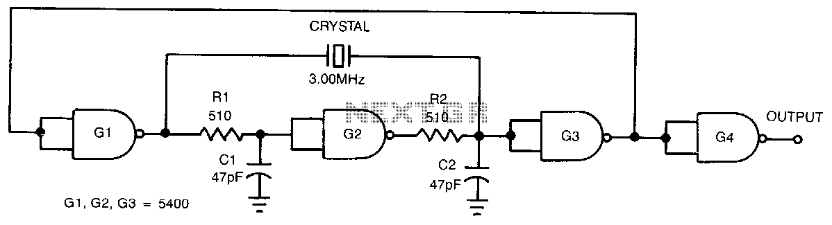
This low-cost, crystal-controlled oscillator employs a single TTL gate. Two key factors facilitate the oscillator's start-up: the configuration of NAND gates G1, G2, and G3 in an unstable logic state, and the high loop gain provided by the three...