
Crystal testing

A simple crystal testing circuit can be designed using a few essential components, typically including a power source, a resistor, a capacitor, and an LED or a multimeter for indication. The primary function of this circuit is to determine the resonant frequency of the crystal and to check if it is functioning correctly.
The circuit can be structured as follows:
1. **Power Source**: A DC power supply, often in the range of 5V to 12V, can be used to power the circuit.
2. **Resistor**: A resistor (R1) can be connected in series with the crystal to limit the current flowing through it. The value of the resistor can vary, but a common choice is around 1kΩ to 10kΩ.
3. **Crystal**: The crystal under test is connected in parallel with a capacitor (C1). The value of the capacitor should be chosen based on the expected frequency of the crystal. A capacitor value of around 10nF to 100nF is often suitable.
4. **LED Indicator**: An LED can be connected in series with a current-limiting resistor (R2) to provide a visual indication of the crystal's operation. When the circuit is powered, if the crystal oscillates correctly, the LED will blink or illuminate.
5. **Multimeter**: For more precise testing, a multimeter can be connected to measure the frequency output from the circuit. This allows for a more accurate assessment of the crystal's performance.
The circuit is assembled on a breadboard for prototyping. The connections should be made carefully to avoid short circuits. Once assembled, powering the circuit should result in the LED lighting up if the crystal is functioning properly. If the LED does not light up or if the multimeter does not register the expected frequency, further investigation may be required to determine if the crystal is faulty.
This simple circuit provides an effective means for hobbyists and engineers to test and verify the functionality of various crystals in electronic applications.Can anyone point me in the direction of a simple useable circuit i can build for testing crystals? I have seen loads of circuits as i am googling.. 🔗 External reference
Related Circuits
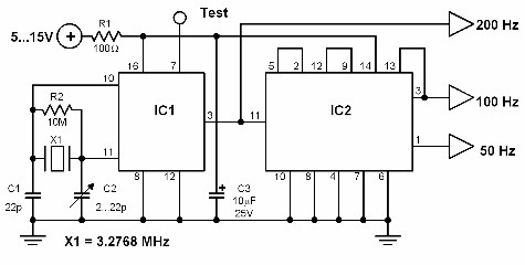
This circuit generates a 50 Hz timebase signal that is independent of the power line frequency. It is designed to provide the 50 Hz signal for electronic circuits that operate specifically with this clock frequency, primarily for circuits and...
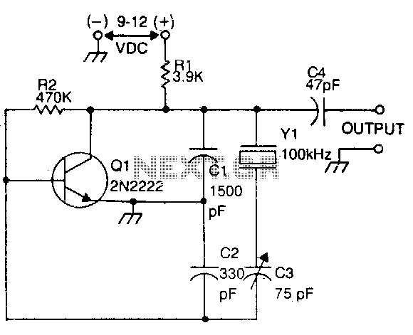
This circuit is commonly utilized by amateur radio operators, shortwave listeners, and various users of shortwave receivers to calibrate the dial pointer. The oscillator functions at a fundamental frequency of 100 kHz, with its harmonics employed to identify specific...
White noise (the sound you hear when a TV is tuned to a non-existent station) has a frequency characteristic which raises the power level by 3dB with each increasing octave, and is not suitable for response testing (and will...
Features: 1. The operating voltage is low, functioning with a single supply of 2.0V. 2. Power consumption is minimal, with a supply current of 5 µA at 32 kHz and 130 µA at 1 MHz. 3. It has a...
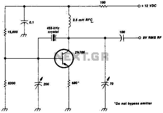
This crystal-oscillator circuit utilizes a 455-kHz crystal. It is a straightforward project. The crystal oscillator circuit based on a 455-kHz crystal operates by utilizing the piezoelectric properties of the crystal to generate a stable frequency. The circuit typically consists of...
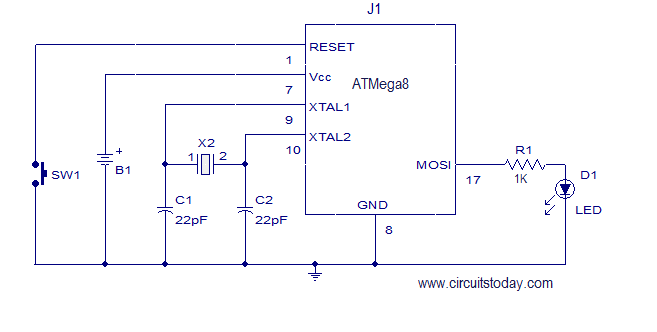
This article explains how to add a 32K external crystal/clock source to the Atmel AVR microcontroller Atmega8, including a circuit diagram and a C program. The Atmel AVR microcontroller Atmega8 is a popular choice for various embedded applications, often requiring...