
Pink Noise Generator for Audio Testing

To create a circuit that generates pink noise from white noise, a combination of a white noise generator and a 3dB/octave filter is required. The white noise generator can be implemented using a simple transistor circuit or a dedicated noise IC, which produces a broadband noise signal. This signal exhibits a flat frequency response across a wide range, typically from 20 Hz to 20 kHz.
The filter circuit can be designed using operational amplifiers (op-amps) configured as low-pass filters. The filter should be designed to provide a roll-off of 3dB per octave, which can be achieved using multiple stages of RC (resistor-capacitor) filtering. Each stage of the filter will contribute to the overall frequency response, ensuring that the power level decreases by 3dB for each octave above the cutoff frequency.
For example, if the cutoff frequency is set at 1 kHz, the filter will allow frequencies below 1 kHz to pass while attenuating those above it. This ensures that the power levels in the lower frequency bands are equalized with those in higher frequency bands, thus approximating the pink noise characteristic.
The output of the filter can be monitored using an oscilloscope or a spectrum analyzer to verify the desired frequency response. Additionally, care should be taken to ensure that the output level is suitable for the connected audio equipment to prevent damage, particularly to tweeters, which are sensitive to high-frequency signals.
Overall, this circuit provides an effective means of generating pink noise for various applications, including audio testing and sound masking, by transforming the broadband white noise into a more balanced frequency output.White noise (the sound you hear when a TV is tuned to a non-existent station) has a frequency characteristic which raises the power level by 3dB with each increasing octave, and is not suitable for response testing (and will probably blow your tweeters as well). By combining a 3dB / octave filter and a white noise source, we can get a very good approximation to "perfect" pink noise, where the power in the octave (for example) 40 to 80Hz is exactly the same as in the octave 10kHz to 20kHz.
🔗 External reference
Related Circuits
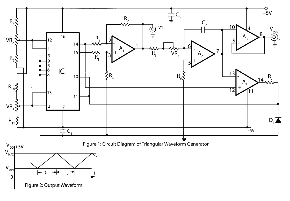
The triangular wave generator featured on this website offers significant advantages, including a circuit diagram and a detailed description of its operation, focusing on achieving maximum and minimum peak levels of the triangular wave. The triangular wave generator is an...

This circuit is for an audio equalizer that is commonly found in commercial products such as high-fidelity systems, car audio, and stage equipment; however, published circuits for these devices are quite rare. This design features equalizer bands. The circuit...
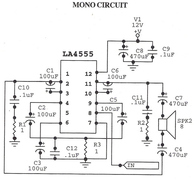
The LA4555 audio amplifier schematic includes both stereo and mono configurations. The LA4555 is primarily designed as a stereo amplifier, delivering 2.3 watts of power into 4-ohm speakers. The LA4555 audio amplifier is an integrated circuit designed for audio amplification...
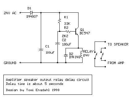
The following circuit illustrates a BC547 transistor used in an output relay delay audio amplifier circuit diagram. Features include the immediate disconnection of the speaker when the... The BC547 transistor is a widely utilized NPN bipolar junction transistor, often employed...
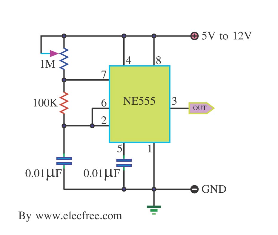
This is a simple pulse generator circuit or standard astable oscillator circuit for the IC 555 timer, NE555N IC. The astable oscillator circuit utilizing the NE555 timer IC serves as a versatile pulse generator, producing a continuous square wave...
The ongoing debate regarding the superiority of valves versus transistors is not the focus here. However, for those uncertain about their choice, this simple amplifier serves as an excellent experiment. The design employs a valve as a pre-amplifier and...