
Current Loop Light Level Detector

This circuit operates in a floating mode, where shorting the supply pin to the output pin disables the upper half of the final push-pull output stage within the IC. This configuration leads to the output current becoming independent of any positive input signal, resulting in a fixed quiescent current drawn from the loop. When a negative signal is applied to the input, the final output stage activates and generates a saturated current in response to input voltages as low as a few hundred microvolts.
The use of the LM10 as a voltage reference ensures stability and precision in the detection of light levels. The operational amplifier within the circuit amplifies the differential signal from the light sensor, enabling it to respond effectively to variations in light intensity. The current loop configuration allows for long-distance signal transmission while minimizing the impact of noise, making it suitable for various applications, including industrial automation and environmental monitoring.
The circuit design emphasizes efficiency and reliability, ensuring that the output signal can be accurately monitored and measured without interference from the power supply. This makes it a valuable tool for engineers and technicians working in fields requiring precise light level measurements.This circuit is two wire light level detector, we don`t separate wires for power this sensor system and for delivering the output signal. With current loop, we do both function in a single pair of cable, just provide the voltage supply and measure the current as the output signal.
The core of this circuit is LM10 voltage reference and op-amp integ rated circuit, operating in floating mode. By shorting the supply pin to the output pin, the upper half of the final push-pull pair inside the IC will be disabled, making the output current is not related with any positive input signal, so a fix quiescent current will be drawn from the loop. At negative signal of the input, the final stage begin working and will produce saturated current at few hundreds micro-volts input.
Be the first of your friends to get free diy electronics projects, circuits diagrams, hacks, mods, gadgets & gizmo automatically each time we publish. Your email address & privacy are safe with us ! 🔗 External reference
Related Circuits
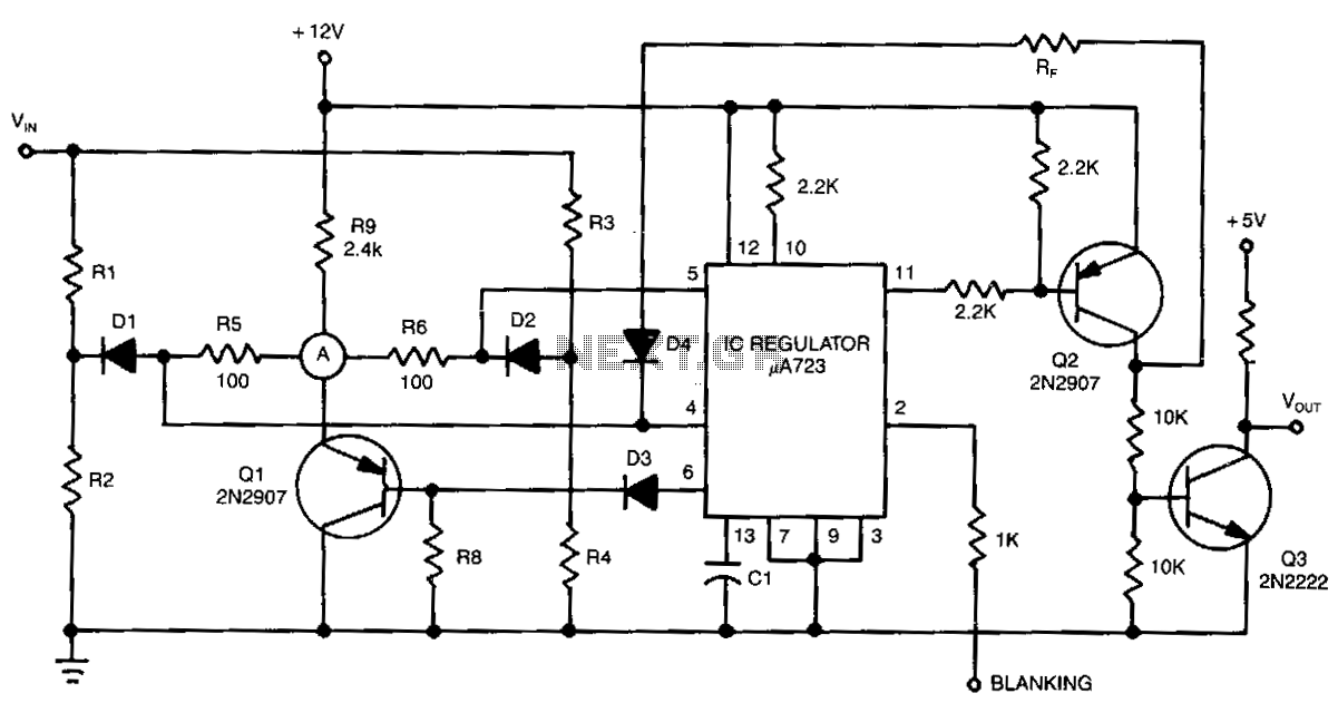
The detector circuit compares the output voltage of two separate voltage dividers with a fixed reference voltage. The resultant absolute error signal is amplified and converted to a logic signal that is TTL compatible. The described detector circuit serves as...

When connecting this element in a voltage divider configuration, a high and low signal can be generated based on the amount of light detected by the sensor. An NPN transistor configured as an inverter further filters this signal to...
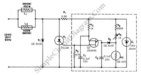
This circuit utilizes a controlled half-plus-fixed half-wave phase control method to regulate an 860-watt lamp load, allowing operation from half to full power. The circuit employs a phase control technique, which involves adjusting the phase angle of the AC...
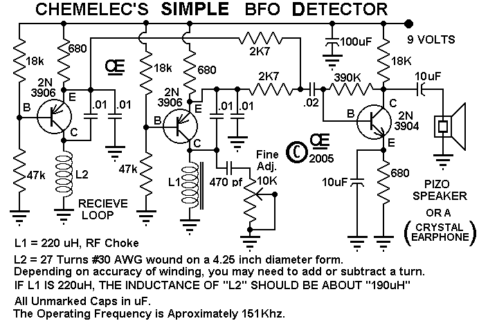
A Very Simple "Beat Frequency Oscillator" type of Metal Detector. These are about the Simplest of all Metal Detector types, But still quite useful for many Detecting applications. And although this one is particularly simple, it works very well. The...
The electronic switch consists of the CK-4 type magnetic control switch and the components VT1, R1, and R2. When the bathroom door is closed, the permanent magnet ZT and the reed switch GA come into proximity, which separates the...
One of the most challenging issues in an audio system is the presence of ground loops. These loops not only introduce hum but can also pick up interference from electric drills, computer hardware, and even AM radio stations. Eliminating...