
Low Cost Precision Light Control / Dimmer

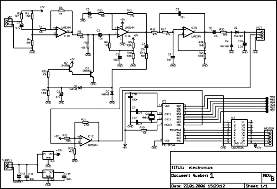
The circuit employs a phase control technique, which involves adjusting the phase angle of the AC voltage applied to the load. This method is particularly effective for varying the power delivered to resistive loads, such as incandescent lamps. The controlled half-plus-fixed half-wave approach combines elements of both half-wave and full-wave control, providing a smoother transition between power levels and reducing flicker in the lamp output.
The schematic typically includes a triac or a thyristor as the primary switching device, which is triggered at a specific phase angle determined by a control circuit. A zero-crossing detector may be integrated to ensure that the triac is triggered at the optimal point in the AC cycle, minimizing electromagnetic interference and improving efficiency.
Additional components such as resistors, capacitors, and possibly an opto-isolator may be included in the control circuit to provide isolation and to shape the control signal. The use of feedback mechanisms can enhance stability and accuracy in power regulation, ensuring that the lamp load operates effectively across the desired range.
Overall, this circuit design is suitable for applications requiring precise control of incandescent lighting, allowing for energy savings and improved user comfort through adjustable brightness levels.Using a the controlled-half-plus-fixed-half-wave phase control method, this circuit can regulate an 860 a watt lamp load from half to full power. This circuit.. 🔗 External reference
Related Circuits

The RF engineer often needs an instrument that can reliably and quickly test a low-frequency quartz crystal unit. However, such equipment is challenging to find, and engineers frequently consult electronic circuit handbooks for schematics that can accomplish this task....
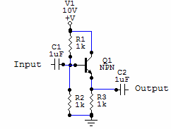
Two examples of the most common types of Voltage followers (buffers). You can find some theory behind them in our amplifier gain and buffer amplifier pages. This first circuit is a very simple one transistor voltage follower. Consists of...
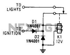
A relay and two diodes are all that is needed; the relay performs the job of a buzzer, so no annunciator is required. When the lights are left on while the ignition is off, the normally closed relay contacts...
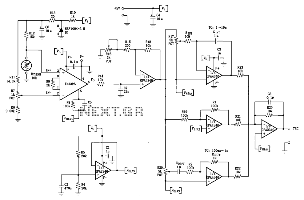
The INA326/327 forms a single power PID (proportional-integral-derivative) controller as illustrated in the temperature control loop. This circuit is primarily designed for temperature measurement and control. A thermistor, designated as RTHERM, detects temperature changes and converts them into an...
This tester, the logic level digital signals indicate on a 7-segment display. The display shows an H as the input signal is high. When the signal is low, the display shows an L on. If the input is open,...
External circuit converts bass beat of music into pulses. The motor is controlled by them. If there's bass beat recognized then the motor rotates one direction (in full stepping) for a predefined time then stops. If the second beat...