
Current to voltage converter proofing

The schematic in question presents a T connection that is straightforward, allowing for easy interpretation of the connections. However, the cross connection introduces ambiguity, which can lead to misinterpretation of the circuit's functionality. In standard electronic schematics, junction dots are critical for indicating where connections are made. Their absence at the cross connection can lead to confusion regarding whether the components are intended to be connected or are simply crossing without any electrical interaction.
In this specific case, the mention of the bottom of the I and the right side of R2 suggests that these points are meant to be grounded. Grounding is a common practice in electronic circuits, as it provides a reference point for voltage levels and helps in stabilizing the circuit. If the schematic indicates otherwise, it raises concerns about the accuracy of the design.
Attention to detail is imperative in circuit design, as any oversight can result in functional issues or even damage to components. The criticism regarding sloppiness highlights the importance of adhering to standard conventions in schematic representation. This includes ensuring that all connections are clear and that the schematic accurately reflects the intended design.
The discussion surrounding the origin of the schematic emphasizes the responsibility of the individual who presents the circuit. Regardless of the source, clarity and adherence to conventions must be maintained to ensure that the schematic can be easily understood and accurately implemented. If the cross at the bottom is indeed a no-connection point, it fundamentally changes the interpretation of the circuit, necessitating a thorough review and correction of the schematic to prevent any potential issues in practical applications.At a T connection, it`s clear, but at a cross it`s otherwise not clear, especially if there are no junction dots elsewhere as in your schematic. It looks like the bottom of Is and the right side of R2 are supposed to be connected to ground, but your schematic says otherwise.
Attention to detail matters. -1 for sloppiness and thinking you are above the standard conventions. I guess you should tell that to the publisher; it looks like it`s from a textbook. (In which case all schematics in the book will be like that :-) stevenvh Aug 28 `12 at 13:10 @stevenvh: No, it`s not my issue where the OP got the schematic from. I don`t care if he drew it himself on a napkin, used schematic software himself, or copied it from elsewhere.
He is the one that posted it here, so he has the responsibility for it. There is lots of crap on the internet. It is in no way acceptable to post crap just because you saw it elsewhere. Olin Lathrop Aug 28 `12 at 22:50 I agree with Olin Lathrop. If the cross at the bottom is no connection then the problem becomes a completely different one Federico Russo Jul 29 `13 at 13:19 🔗 External reference
Related Circuits
This current-limiting circuit, illustrated as part of a small bench power supply, can be utilized with any dual-rail current source. The section of the circuit to the left limits the current at the input to the dual voltage regulator...

An analog-to-digital converter (ADC) transforms an analog input voltage into a digital value. This circuit illustrates the operation of an ADC, utilizing the ATmega8 microcontroller to control its functionality. The resolution of the converter denotes the number of discrete...

The circuit's current exceeds the load carried by the rated current meter, prompting the user to immediately cut off the power supply to address the overload. Pressing the reset button restores power, making the system simple, convenient, and practical....

This circuit utilizes a programmable operational amplifier, specifically the HA2730, which is a two-amplifier monolithic chip featuring independent programming ports for each amplifier. The parameters of the amplifiers, including the slew rate, vary linearly based on a set current....
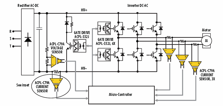
Insulated-gate bipolar transistors (IGBTs) require comprehensive protection to prevent damage and failures due to conditions such as short circuits, overloads, and overvoltages. This protection is essential for ensuring safe and stable operation of power converters in applications including motor...
The Car Voltage Gauge is based on 3 parts. The input circuit is an Analog to Digital Converter (IC2 CA3162E). The purpose of this chip is to sample an analog voltage and convert it to a decimal value which...