
CW 250mW transmitter


TX
L1 is 28 turns on an RS273-101 former wound with original wire
L2 is 11 turns wound on an RS273-102 former, wound with original wire
T1 primary is 50 turns wound on an RS273-101 former, wound with original wire
T1 secondary is 22 turns wound on top of primary, wound with original wire
PA
L1 is 11 turns on an RS273-101 former, wound with original wire
L2 is 100 turns on an RS273-101 former, wound with original wire
L3 is just 3 turns wound over L2 using 22 SWG enameled wire
L4 is 5 turns wound over L2 using 22 SWG enameled wire
L5 is 18 turns 12mm dia x 30mm long using 22 SWG enameled wire
L6 is 18 turns 12mm dia x 30mm long using 22 SWG enameled wire
The described HF transmitter circuit is a compact design suitable for amateur radio applications, specifically optimized for the 7 MHz band. The core components include two BC547 transistors, which serve as the primary amplification elements. The circuit is designed to provide a power output exceeding 250 mW in its basic configuration, with potential modifications to accommodate all HF bands.
Keying for continuous wave (CW) operation is facilitated by manipulating a resistor in the emitter circuit of the second transistor (TR2). By disconnecting the 56-ohm resistor and connecting it to ground via a key, users can achieve effective keying. For applications requiring longer keying envelopes, increasing the capacitance of the 10 nF capacitor in the emitter of TR2 is recommended, allowing for a more gradual rise and fall in output power.
An optional power amplifier (PA) stage can be integrated to boost the RF output to over 3 watts. The third transistor (TR3), typically a TO220 package type, can be selected from a variety of models, with suggestions including the "JECL45-02" and "C2078." The flexibility in transistor choice allows for experimentation with different devices, which has proven successful in various builds.
The inductors and transformers are constructed using original wire from TANDY RF chokes, ensuring compatibility with the circuit's design requirements. The winding specifications for the transmitter (TX) section are as follows:
- L1: 28 turns on an RS273-101 former.
- L2: 11 turns on an RS273-102 former.
- T1 (transformer): 50 turns for the primary and 22 turns for the secondary, both wound on the RS273-101 former.
For the PA section, the inductor and transformer specifications are:
- L1: 11 turns on an RS273-101 former.
- L2: 100 turns on an RS273-101 former.
- L3: 3 turns wound over L2 using 22 SWG enameled wire.
- L4: 5 turns wound over L2 using 22 SWG enameled wire.
- L5 and L6: Each consists of 18 turns, wound on a 12 mm diameter by 30 mm long form, utilizing 22 SWG enameled wire.
This configuration allows for effective RF signal generation and amplification, suitable for hobbyists and amateur radio operators looking to experiment with HF transmission. The flexibility in component selection and winding techniques can lead to varied performance characteristics, making this circuit an excellent platform for learning and development in RF electronics.Here is a simple little HF TX. It may be modified for all the HF bands, but the details given are only for the 7MHz band. The basic transmitter uses two transistors; BC547 (as usual) and will deliver over 250mW of power. CW keying may be achieved by disconnecting the 56 ohm resistor in the emitter of TR2, and connecting it to ground via the key. Increase the value of the 10nf in the emitter of TR2 if you need longer time-constant keying (keying envelope).
The optional PA stage will increase the RF output of the HF TX to over 3 watts. TR3 is one of those TO220 plastic transistors found in CB set PAs, I will leave the choice up to you as there are hundreds of them. The LAST one I used has the marking: "JECL45-02", although I have never been able to identify it properly. I recently received E-mail from one amateur who recomends "C2078"). I have built several PAs with 100% success using different transistors on each occasion. The coils are mainly wound on a TANDY (Radio Shack) RF choke. Do not discard the original wire removed from the chokes as this will be used. You may want to try using different former material. I built one of these transmitters and wound the coils on some long-thin ferrite beads after gluing some wire in the hole at each end.
The beads were about 3mm dia x 15mm long. . TX L1 is 28 turns on an RS273-101 former wound with original wire L2 is 11 turns wound on an RS273-102 former, wound with original wire T1 primary is 50 turns wound on an RS273-101 former, wound with original wire T1 secondary is 22 turns wound on top of primary, wound with original wire . PA L1 is 11 turns on an RS273-101 former, wound with original wire L2 is 100 turns on an RS273-101 former, wound with original wire L3 is just 3 turnswound over L2 using 22 SWG enameled wire L4 is 5 turns wound over L2 using 22 SWG enameled wire L5 is 18 turns 12mm dia x 30mm long using 22 SWG enameled wire L6 is 18 turns 12mm dia x 30mm long using 22 SWG enameled wire
🔗 External reference
Related Circuits

This design outlines a tracking transmitter for audio tones operating in the FM band frequency. The circuit can function as either a signal transmitter or a remote control transmitter and utilizes only readily available components. It has a transmission...
The AM transmitter circuit consists of an audio amplifier and an RF oscillator. The oscillator is constructed around transistor Q1 and its associated components. The tank circuit, which includes inductor L1 and variable capacitor VC1, is tunable from approximately...
This 2-meter 144 MHz fox hunt transmitter is utilized in amateur competitions where a concealed transmitter is to be "hunted" using primarily homemade receivers. The 2-meter 144 MHz fox hunt transmitter is designed for use in amateur radio competitions, commonly...
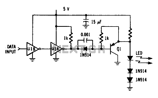
The driver circuit utilizes an MC74LS04 and a discrete transistor. The circuit is capable of driving the LED (MFOE12QO) at data rates of up to 1 Mbps. The driver circuit employs the MC74LS04, which is a hex inverter, to provide...
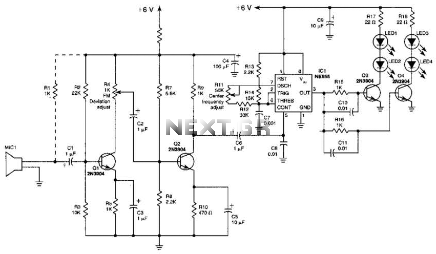
This transmitter employs a two-stage amplifier configuration using transistors Q1 and Q2 to frequency modulate an NE555 timer, which is set up as a voltage-controlled oscillator (VCO) operating at approximately 50 kHz. The resulting frequency-modulated pulse train is transformed...
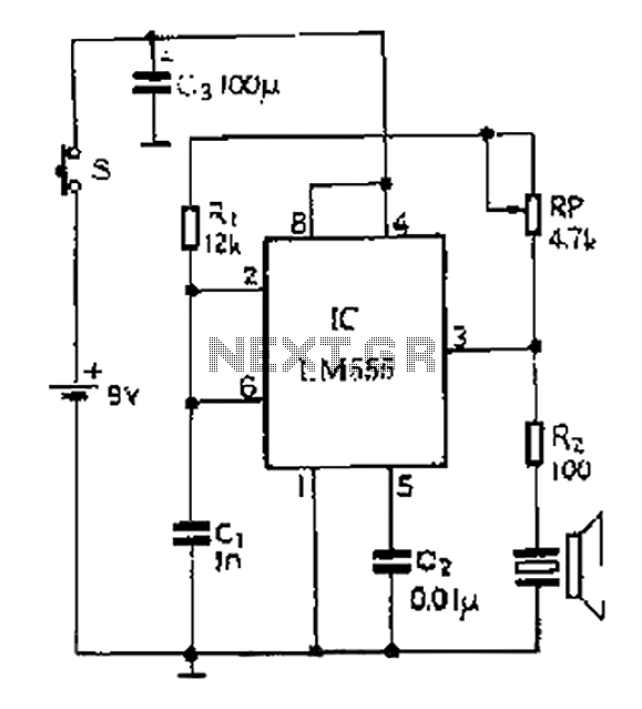
A 40 kHz ultrasonic transmitter circuit utilizes the LM555 timer as a time base circuit along with external components to create a 40 kHz multivibrator. The resistance of the adjustable resistor RP can modify the oscillation frequency. The output...