
Fm Light-Beam Transmitter Circuit

The circuit begins with the NE555 timer configured in astable mode to function as a VCO. The frequency of the output signal can be adjusted by varying the resistors and capacitors connected to the timer. The two-stage amplifier, comprising Q1 and Q2, amplifies the modulating signal before it is fed into the NE555 timer. This ensures that the modulation is strong enough to produce a detectable output at the desired frequency.
Transistors Q1 and Q2 are typically configured in a common-emitter arrangement, providing both voltage gain and current gain. The output from the second stage is connected to the control voltage input of the NE555, allowing for effective frequency modulation. The modulation index can be adjusted by changing the amplitude of the input signal, which directly influences the deviation of the carrier frequency.
The output from the NE555 is a pulse train that varies in frequency based on the modulating signal. This pulse train is then utilized to drive a series of light-emitting diodes (LED1 to LED4). Transistors Q3 and Q4 serve as drivers for the LEDs, allowing them to handle higher current levels than what the NE555 can provide directly. This configuration ensures that the LEDs can operate efficiently and produce a visible light output.
The entire assembly is suitable for applications in optical communication systems, where the modulated light pulses can be transmitted over distances and detected by photodetectors. The design can be further enhanced by incorporating additional stages for improved modulation depth or by using different types of LEDs for varying wavelengths of light. This transmitter uses two-stage amplifier Q1/Q2 to frequency modulate an NE555 (configured as a VCO) operating at about 50 kHz. The resultant FM-modulated pulse train is converted to light pulses via LED1 through LED4, driven by Q3 and Q4.
Related Circuits
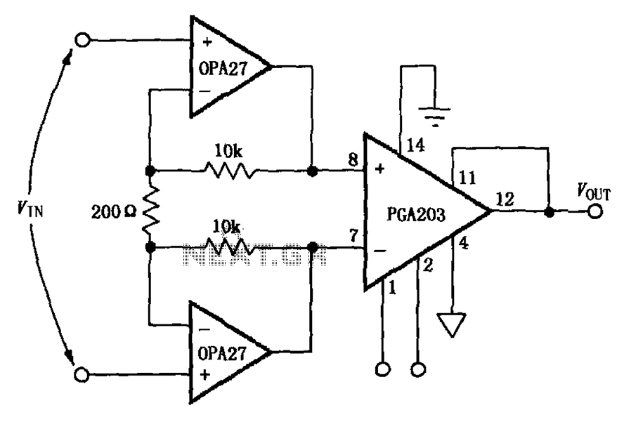
The circuit depicted in the figure features a PGA203 operational amplifier (op amp) and two OPA27 op amps, forming a low-noise differential amplifier. The input stage utilizes the PGA203 in conjunction with the two OPA27 op amps. The non-inverting...

A 2002 Blazer was diagnosed with error codes P0155 and P0756, indicating a malfunction in the O2 sensor heater circuit and a performance issue with the shift solenoid B circuit. The vehicle initially has power, but it loses power...
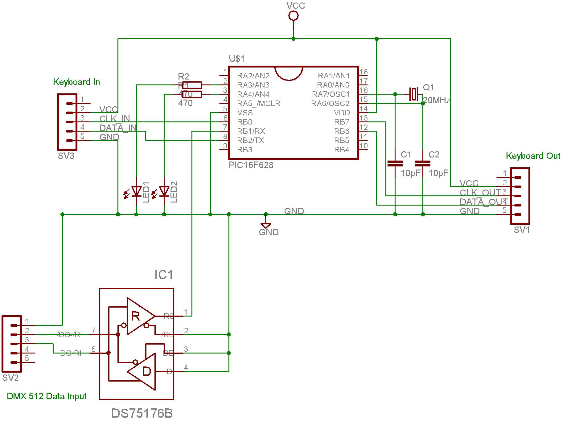
This system is designed for use with a PC connected to video projectors, enabling a lighting controller to manage a presentation displayed on the video screen. The PC used for the presentation is situated in a different location from...

CB85-10 leakage protection circuit diagram, T for the trip coil, SB is the test button, Ri is simulated human resistance. The CB85-10 leakage protection circuit is designed to enhance safety by detecting leakage currents and disconnecting the electrical supply to...
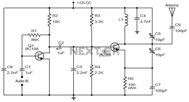
Numerous FM transmitter circuits have been published, and this is another example of a simple two-transistor FM transmitter. The first stage of the circuit is a preamplifier based on transistor Q1. This stage operates as a collector-to-base biased amplifier,...

A new member has joined the forum and is seeking assistance with electronics, particularly from a technical engineering perspective, although they have some experience with circuits and schematics. The individual is likely looking to enhance their understanding of electronic components,...