
Cybernetic Micro Systems

The CYB-P51 (Rev A) Prototyping Board serves as a versatile platform for developing and testing applications based on the P-51 microcontroller. The board's two-layer design, while lacking dedicated power and ground planes, provides ample space for component placement and circuit routing. The inclusion of through-hole components facilitates easy modifications and troubleshooting, making it suitable for prototyping environments.
The oscillator circuit, featuring a 20 MHz oscillator, is crucial for timing operations within the microcontroller. The ability to connect the oscillator to 3V at jumper W5 ensures compatibility with the P-51's voltage requirements. The crystal circuit pattern allows for flexibility in test setups, accommodating different clock sources as needed.
The reset functionality, enabled by an external pushbutton switch, allows users to reset the board without removing it from the ISA slot, enhancing convenience during testing. The DIP switch configuration for base address selection and software-selectable IRQ adds to the board's adaptability in various applications.
Power management is efficiently handled by the onboard voltage regulator, which converts the 5-volt supply from the computer system to the necessary 3.3 volts for both the P-51 and the oscillator. This ensures stable operation of the microcontroller and its peripherals. The I/O pins are designed to operate at 3.3 volts while being tolerant of 5 volts, providing a degree of interoperability with other devices.
The wire-wrap patterns at the bottom of the board facilitate easy access to ISA-bus signals, allowing for straightforward interfacing with other systems or components. The 40-pin wire-wrap pattern for application signals mirrors the standard 8051 DIP configuration, simplifying integration with existing designs.
Attention to signal integrity is emphasized through design recommendations, including the need for buffering when driving signals off-board and the separation of noisy circuitry from sensitive components. The inclusion of GND posts along the wire-wrap pattern enhances grounding practices, which is critical for maintaining signal quality and reducing electromagnetic interference.
Overall, the CYB-P51 (Rev A) Prototyping Board is a well-thought-out design that balances functionality, ease of use, and adaptability for a wide range of development and testing scenarios involving the P-51 microcontroller.The CYB-P51 (Rev A) Prototyping Board is designed as a two layer board (without power and ground planes). All components, except the premounted P-51, are through-hole for easy probing and replacement of parts.
The board has an oscillator circuit and a crystal circuit pattern, so that either may be used in the test application. A 20 MHz Oscillator is provided, as shown in this photo, and it is connected to 3V at jumper W5, as required by the P-51. See the clock circuits in the user manual for support components for the Xtal circuit. An External pushbutton switch can Reset just the board while in an active ISA slot. The host software must release this hard reset of the P-51 (see P-51 Code RAM in manual). The base address from the ISA host is switch selectable on a DIP-switch that is accessible from outside the computer.
The required IRQ is software selectable. See the P-51 user manual for switch settings. On-board Voltage regulator provides 3. 3 volts to the P-51 and oscillator using the computer system`s 5-volt supply. The P-51 I/O pins drive 3. 3 volts and are 5-volt tolerant. All of the ISA-bus signals are brought to a wire-wrap pattern at the bottom of the board, and all the P-51-to-ISA/PC104 signals are also available at that pattern. Alternatively, a micro-controller host could interface to the P-51 at that same jumper. The application signals of the P-51 are brought to a 40-pin wire-wrap pattern in the same configuration as a standard 8051 DIP (with optional IDC pattern).
All 8051 signals except X1, X2, Reset, EA, and PSEN are available at the 8051 pattern. Note that a row of GND posts (indicated by white circles) runs along the end of the pattern. Of the excluded 8051 signals, X1 and X2 are available at the Xtal circuit, Reset is replaced by ResetDrv from the ISA-bus, and EA and PSEN are not implemented in the P-51. Pin 40 of the 8051 socket (J3) is not connected to power. Jumper W8 allows you to connect that pin to 3 or 5 volts, or leave it open; and an LED indicates whether power appears on that pin.
Two RJ-45 jack patterns allow sixteen signals to be brought outside the system chassis. These are provided but are not mounted on the board. Alternatively, a 3x3 wire-wrap grid is also available at each location. As a matter of good design practice, the signals from the P-51 should not be driven off-board without buffering, and should be protected from noisy circuitry. Your low-noise digital circuitry should be added to the on-board wire-wrap area, rather than cabling to a neighboring board.
Noisy circuitry should be separated and buffered from the 3-volt area. Your production design should include a ground plane with a good grounding connection to all eight P-51 ground pins. An ISA-bus Extender is not recommended since it may introduce noise. 🔗 External reference
Related Circuits
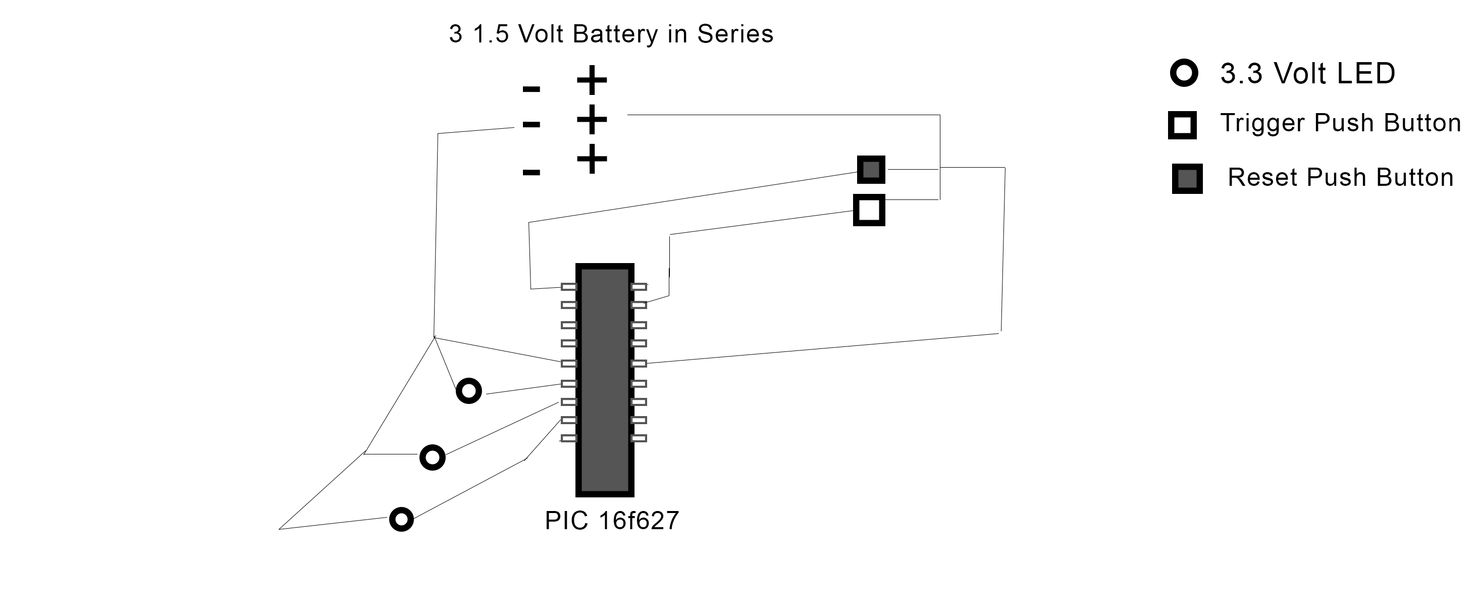
The PIC 16F627 microcontroller has been programmed to activate three LEDs when a trigger pushbutton is pressed. Additionally, when a reset pushbutton is pressed, a shutdown sequence is initiated where each LED turns off sequentially with a 5-second delay...
Carefully examine the following circuit diagram and attempt to construct the circuit on a breadboard first. If it functions correctly, proceed to create its PCB version. The circuit diagram serves as a blueprint for constructing an electronic circuit on a...

The FM Remote Control Receiver, available in the Infra-red circuits section of this website, features a connector that provides an analogue output. To create a simple intercom or public address (P.A.) system, the associated transmitter requires a microphone pre-amplifier...
Most inverters available in the market utilize a modified sine wave to achieve better output at a competitive cost. The modified sine wave unit employs a 50% fixed PWM square wave, with the peaks balanced by a capacitor to...
The MC33411 900 MHz Analog Cordless Phone Baseband system is designed to meet the specifications of a 900 MHz Analog cordless telephone system. It includes three Phase-Locked Loops (PLLs). Two of these PLLs are intended for use with external...
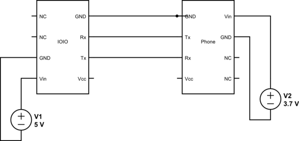
This project utilizes Sparkfun's IOIO for Android, focusing on power consumption concerns. The IOIO board can provide the phone with 500 mA charging, which may be excessive for continuous operation. The proposed solution is to power both the phone...