
microcontroller Can I cut off the 5v output of the IOIO to the Android

The project entails a detailed understanding of power management and serial communication between the IOIO board and an Android device. The IOIO board is designed to interface with Android applications, enabling control of various hardware components. To achieve optimal performance while minimizing power consumption, the project suggests using a shared external power supply for both the IOIO and the phone.
The proposed circuit configuration includes a power supply unit capable of delivering 5V for the IOIO board and 3.7V for the phone. The connection from the power supply to the IOIO board should include a current limiting trimmer resistor, allowing for fine-tuning of the current supplied to the board. This adjustment is vital, as excessive current can lead to overheating and potential damage to the components.
The serial communication lines (Rx and Tx) can be connected directly to the IOIO, allowing for data transfer without the need for USB data lines, which are not utilized in this context. The GND line must also be connected to ensure a common reference point for both devices.
In summary, the project emphasizes the importance of efficient power management and proper communication protocols when designing an autonomous system that integrates an Android device with an IOIO board. By carefully managing power consumption and utilizing the available hardware features, the project aims to create a reliable and efficient solution for remote operation.Project using Sparkfun`s IOIO for Android ( ) where power consumption is a concern. The IOIO board provides the phone with 500 mA charging if I`m correct, which is too much for continuous operation. There`s a trick I have in mind where I want to power the phone and the IOIO board separately from the same external power source (Of
course the phone gets its 3. 7v while the IOIO gets 5v). The catch here is that I want to cut off the 5v line on the cable from the IOIO to the phone, leaving the GND, Rx and Tx (Which are good enough for any serial transmission). USB doesn`t have the notion of TX and RX lines, it`s not a UART. The data lines are D+ and D- used for bidirectional differential signaling. The VBUS line (which you refer to as Vcc) is essential for detection the presence of the host (IOIO in this case), so what you`re suggesting will not work.
The best you can do is use the current limiting trimmer that`s on the IOIO. Start with it fully clockwise, then, with the Android connected, turn it counter-clockwise until the connection drops, then back some. The minimum current that can be achieved like that varies by phone model. Also, turning the screen and comms off on the Android will reduce current significantly provided the phone battery is fully charged.
@AhmedFarid Ytai`s answer is correct. The VBUS/VCC on the usb cable is required for the connection to work. The trimmer is the only way to change how much current draw is allowed. But the real question is, if you are powering both from the same external supply, why Are you regulating the 5v down to 3. 7v The phone would be more efficient at doing that itself from it`s normal 5v charging. Passerby May 29 `13 at 5:36 Never thought the creator himself would answer my question! I never noticed the limiter thing. This is best way to go for me. Thanks Ytai! Ahmed Farid May 29 `13 at 8:19 @Passerby Input directly to the phone is a better option indeed, but I have the issue of having a single battery system supporting every component in my project.
In other words, I`m not using the phone`s battery. This I believe leads to the need to connect both of them separately and reduce current draw as much as possible. My project is kind of like a robot: remote and autonomous. Ahmed Farid May 29 `13 at 8:25 🔗 External reference
Related Circuits
This simple AVR programmer is capable of transferring hex programs to most ATMEL AVR microcontrollers. It is more reliable than many other simple AVR programmers available and can be constructed in a very short amount of time. This programmer...
Home appliances are typically controlled using switches, sensors, and similar devices. However, physical interaction with switches can pose risks, particularly in the event of short circuits. The circuit presented here eliminates the need for physical contact to operate the...
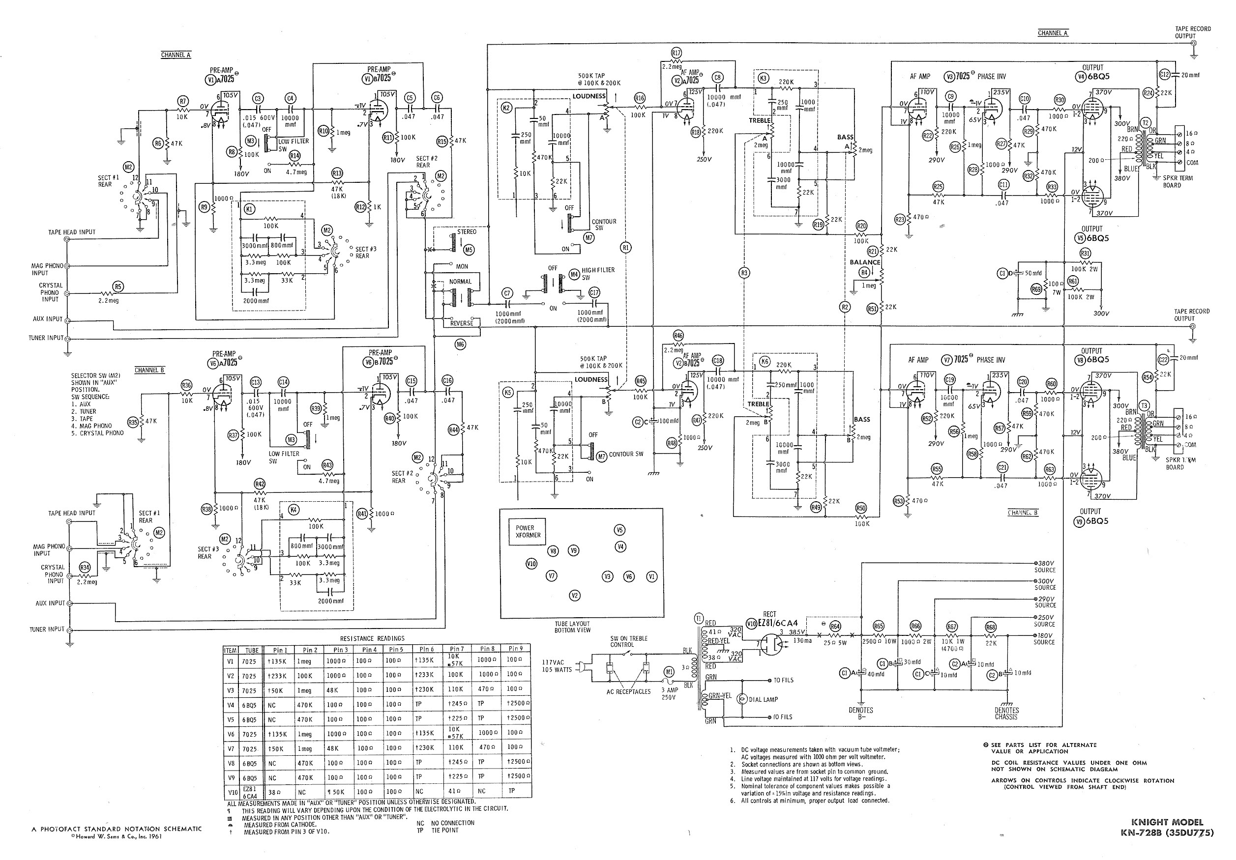
Ty - Concerning the updated schematic of the AF/PI stage, it appears that resistor R45 is not present. Additionally, the disk capacitor bypassing R44 is marked as 68nF750 with a tolerance of 10%, which is presumed to be the...
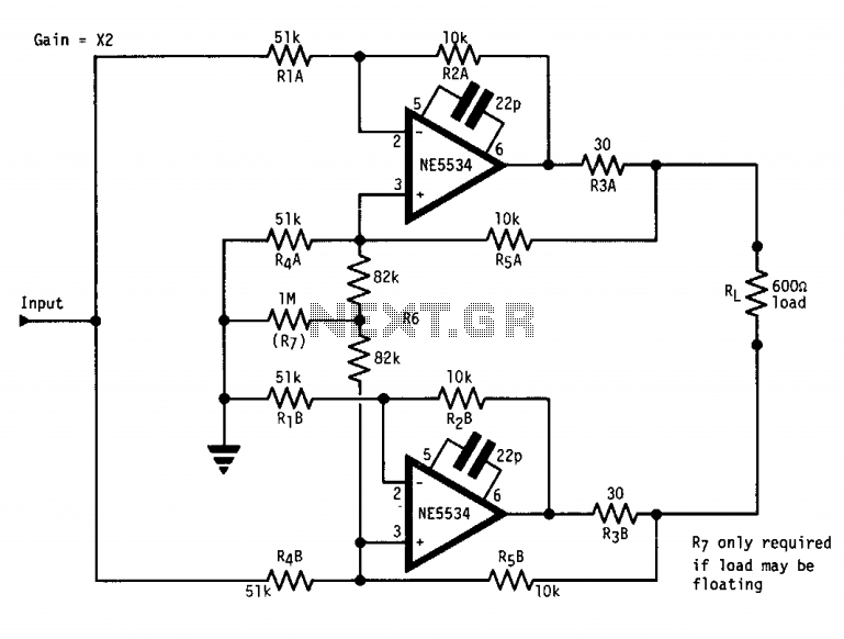
The circuit features a "floating" output, functioning similarly to an isolated transformer winding. The output amplitude remains constant regardless of whether the center or either end of the load is grounded. This is accomplished by ensuring that the output...
This report outlines the operation and adjustment of a Phase Locked Loop (PLL) hum cancellation circuit designed to reduce residual hum from amplifiers. This circuit is particularly useful for Directly Heated Triode (DHT) amplifiers with AC-operated filaments, where a...
The electronics consist of three op-amp circuits; each built around one half of an NE5532 dual op-amp. Each circuit uses that op-amp in a different configuration. The first circuit is a non-inverting pre-amp, the second is a unity-gain phase-inverter,...