
Dancing light

The circuit consists of two primary components: the NE555 timer and the CD4017 decade counter. The NE555 timer is configured in astable mode, meaning it continuously oscillates between its high and low states, producing a square wave output. This output serves as the clock signal for the CD4017, which is a decade counter capable of driving up to ten outputs sequentially.
The configuration of the NE555 involves connecting resistors and capacitors to set the desired frequency of oscillation. The frequency can be adjusted by varying the values of the resistors (R1 and R2) and the capacitor (C1) connected to the timer. The output from the NE555 is fed into the clock input (pin 14) of the CD4017.
As the CD4017 receives each clock pulse, it activates one output pin at a time, starting from Q0 and progressing to Q9. When an output pin goes high, it allows current to flow through the connected LED, causing it to light up. This sequential activation of the outputs gives the appearance of the LEDs dancing or moving in a pattern.
The overall effect can be visually appealing, and the speed at which the LEDs "dance" can be modified by changing the component values in the NE555 configuration. By selecting different resistor and capacitor values, the frequency of the clock pulses can be increased or decreased, thus altering the rate at which the LEDs illuminate.
In summary, this simple dancing light circuit effectively demonstrates the use of an astable multivibrator and a decade counter to create a visually dynamic light display, with adjustable speed controlled by the oscillator's frequency.Here is a simple dancing light circuit based on NE555 (IC1) & CD4017 (IC2). The IC1 is wired as an astable multivibrator to provide the clock pulses for the CD4017. For each clock pulse receiving at the clock input (pin14) of IC CD4017, the outputs Q0 to Q9 (refer pin diagram of CD 4017) becomes high one by one alternatively. The LEDs connected t o these pins glow in the same fashion to give a dancing effect. The speed of the dancing LEDs depend on the frequency of the clock pulses generated by the IC1. 🔗 External reference
Related Circuits
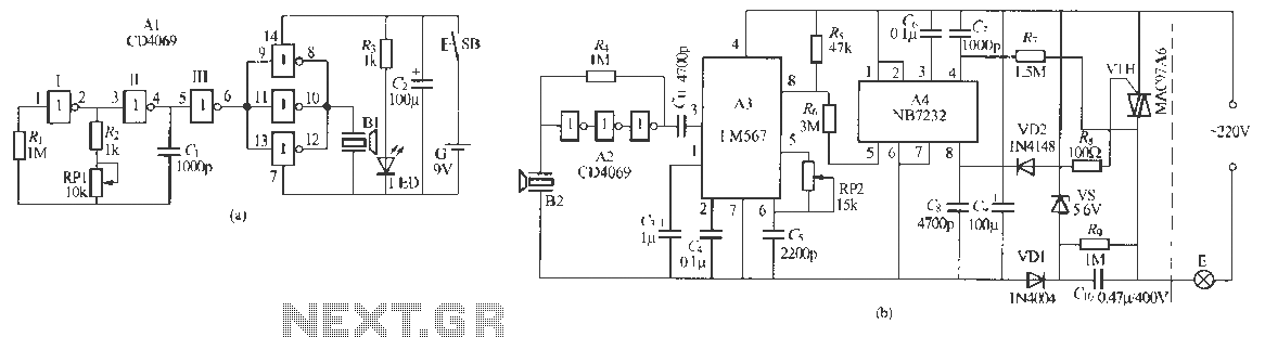
Remote control dimmer lights consist of two parts: an ultrasonic transmitter and an ultrasonic remote control dimmer receiver. The ultrasonic wave transmitter circuit is detailed in A 229 (a). It includes components such as R, R., RP1, and C,...
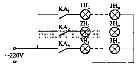
The relay control system utilizes multiple pairs of contacts, allowing for the connection of higher power lamps in parallel. The circuit design is straightforward; by altering the capacitance of the capacitor, different flashing frequencies can be achieved. The described circuit...
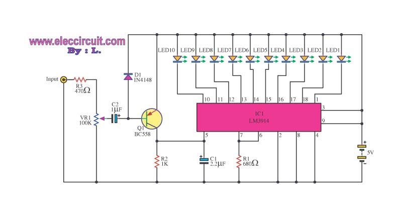
This is a simple light-running circuit synchronized with music. The circuit is straightforward, operating in mono, and requires only a few components. It can be connected to the output of a CD player. The described circuit utilizes a basic audio...
This circuit is continuously connected to a mains socket and is designed to trickle charge nickel-cadmium (Ni-Cd) batteries. In the event of a power outage, the lamp automatically turns on. Alternatively, an alarm sounder can be selected instead of...
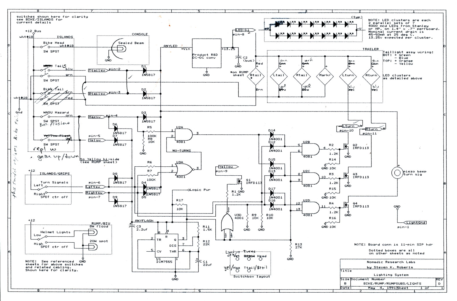
This second issue of the Bikelab Notes, published during the development of BEHEMOTH at Sun Microsystems, focuses on high-brightness LED taillight assemblies that were not commercially available at the time, making this a unique project. The author also comments...
A bright lamp flashes in synchrony with the lightning bolts, indicating the proximity and intensity of the storm. The described circuit operates as a storm warning system, utilizing a bright lamp to provide visual alerts in response to lightning activity....