
High-power lights flashing alternately chain circuit

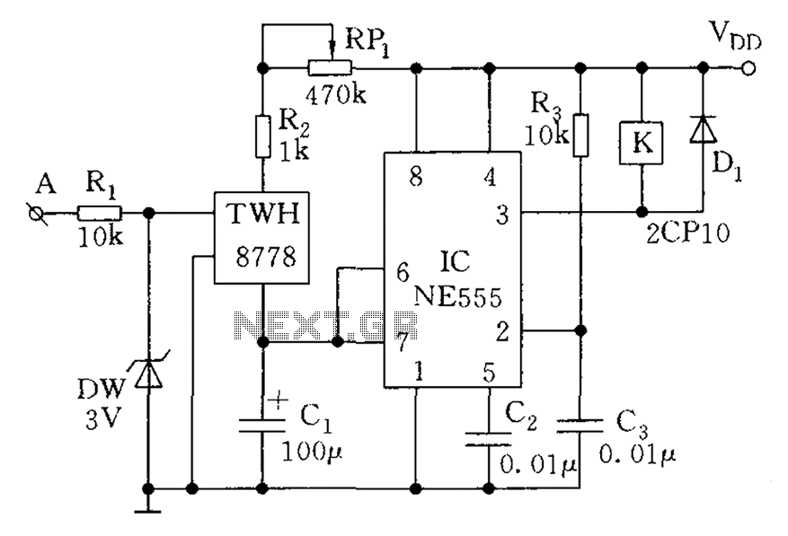
The described circuit employs a relay to control the operation of high-power lamps, which can be connected in parallel to increase total capacity. The relay serves as an electromechanical switch that opens and closes the circuit, enabling or disabling the lamp based on the control signal.
The key component influencing the flashing frequency is the capacitor, which works in conjunction with a resistor to form an RC timing circuit. When the capacitor charges and discharges, it determines the on-off cycle of the relay, thereby controlling the lamp's flashing rate. By selecting capacitors of different capacitances, the time constant of the RC circuit can be modified, resulting in varied flashing frequencies.
In this configuration, it is essential to ensure that the relay contacts can handle the total current drawn by the lamps. Additionally, protective components such as diodes may be included across the relay coil to prevent back EMF from damaging the control circuit when the relay is de-energized.
This simple yet effective design allows for versatile applications in decorative lighting, signaling, or any scenario where variable flashing is required. Proper selection of components and careful consideration of the relay's specifications will ensure reliable operation and longevity of the circuit.As a result of the relay control (several pairs of contacts, if more capacity is connected in parallel), so the lamp power can be large, the circuit is very simple, just change the capacitor capacitance, you can get a different flash frequency.
Related Circuits
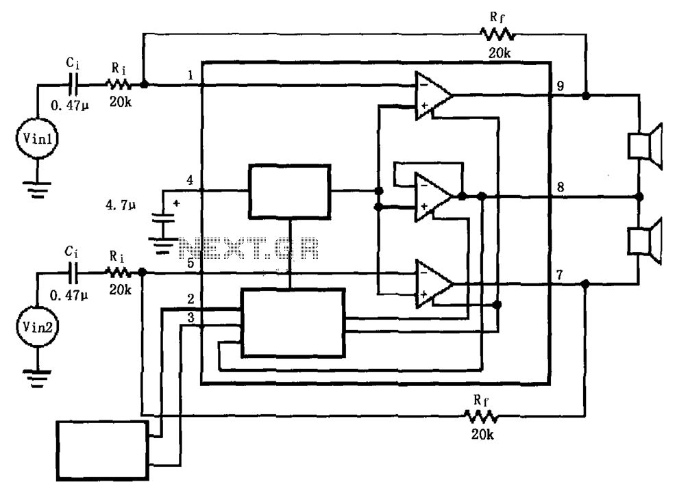
The LM4911 is presented in a configuration that does not utilize an output capacitor (OCL) for its power circuit. This design eliminates the need for squelch control (Mute), as the shutdown control (SD) responds more rapidly than the squelch...
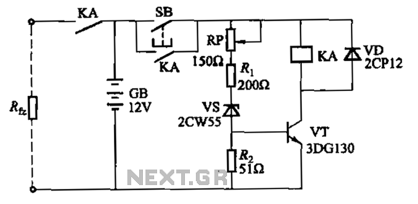
Deep discharge of a battery can lead to plate curing, which shortens the battery's lifespan. To prevent this, a discharge protection device can be implemented. The circuit diagram illustrates this mechanism. When the battery voltage falls to a predetermined...
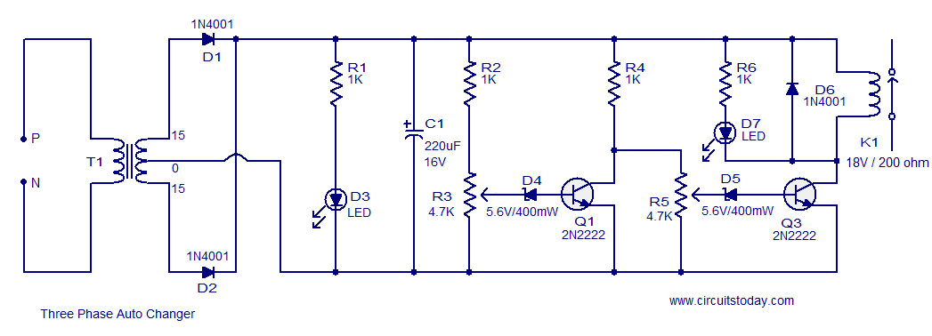
This circuit is a modification of a high and low voltage cut-off with delay and alarm circuit that was featured in Circuits Today. It has been tested and found to be reliable. The circuit can be adapted with minor...
Running Message Display Circuit Diagram. This circuit is based on the CD401 IC. Features: Light emitting diodes are advantageous due to their smaller size. The Running Message Display Circuit utilizes the CD401 integrated circuit, which is a versatile component in...
The count switching circuit consists of an electronic switch and a pulse delay circuit for control. The count switching circuit is designed to manage the switching of signals in a controlled manner. The electronic switch serves as the primary component...
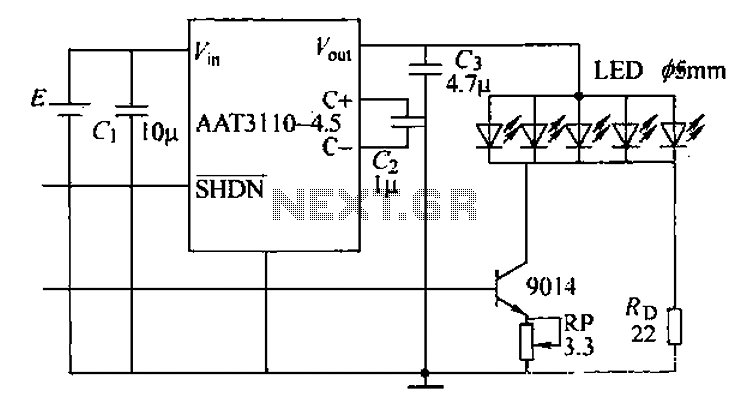
A circuit designed for a phone photo camera flash that delivers a peak current of 200mA. It utilizes the AAT3110-4.5 capacitive charge pump chip to boost and regulate the lithium battery voltage to 4.5V. This voltage powers a series...