
Dark-activated LED or Lamp Flasher

The described circuit utilizes a Bowes/White emitter-coupled multivibrator configuration, which is known for its ability to produce stable oscillations with minimal components. This circuit operates at an oscillation frequency of approximately 1Hz, primarily determined by the capacitance value of capacitor C1. The choice of C1 is critical, as values in the range of 100µF to 1000µF yield optimal performance for the desired flashing frequency.
The circuit includes a photoresistor, which plays a crucial role in controlling the flashing of the LED. When the ambient light level is low, the resistance of the photoresistor increases, allowing the circuit to trigger the LED to flash. The timing and sensitivity of this response can be fine-tuned using resistor R2, which acts as a variable resistor. Adjusting R2 modifies the threshold at which the LED begins to flash, providing flexibility in the circuit’s operation under varying light conditions.
For applications requiring a filament lamp instead of an LED, modifications to the circuit are necessary. A bulb rated between 2.2V and 3V with a current rating of 250-300mA should be used in place of the LED. Additionally, R2 should be replaced with a 10KΩ, 1/2W resistor to accommodate the higher current demands of the filament lamp while maintaining the desired flashing characteristics.
Overall, this circuit offers a simple yet effective solution for creating a flashing light effect in response to ambient light levels, suitable for various applications in visual signaling or decorative lighting. The use of common electronic components makes it accessible for hobbyists and professionals alike.This circuit adopts the rather unusual Bowes/White emitter coupled multivibrator circuit. The oscillation frequency is about 1Hz and is set by C1 value. The LED starts flashing when the photo resistor is scarcely illuminated. The onset of flashing can be set by trimming R2. * Best results in flashing frequency can be obtained using for C1 a value in the 100 - 1000µF range. * To drive a filament lamp make the following changes: Use a 2.2 to 3V, 250-300mA bulb in place of the LED R2 = 10K 1/2W T 🔗 External reference
Related Circuits

An embedded C-based RF-controlled robot equipped with a metal detector, along with wireless image and voice transmission capabilities. This project report is intended for electronics and communication engineering students. The project involves the design and implementation of an RF-controlled robot...
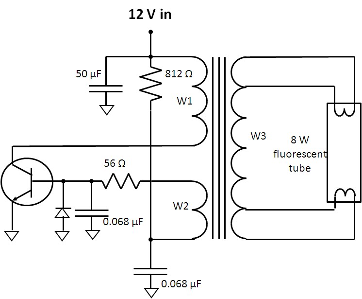
A fluorescent lamp has specific requirements for startup and continuous illumination. The flyback converter is designed to meet these requirements. Initially, attempts to locate a schematic for the fluorescent lamp assembly proved unsuccessful. However, the low parts count and...
This is a simple 1.5V powered LED flasher circuit diagram. This circuit can flash 1.7V or 2.3V LEDs (depending on the color) using a 1.5V DC input. The LED will turn on when the 100µF capacitor is charged by...

This is a nice example circuit that can be used at parties. The four LEDs blink to the beat of the music. The light organ using a microphone responds to sound. T1 amplifies the signal from MIC. The sensitivity...

This white LED floodlight illuminates your porch with cool white light. The circuit features a simple and energy-saving design, with a low current consumption. The LED floodlight circuit typically consists of a power supply, a control circuit, and the LED...

The circuit operates similarly to the original strobes, but utilizes a glowing tube. The glowing tube remains constant, with the two electrodes continuously supplied with electricity. This current activates the two resistance components of the glow tube, causing mercury...