
flyback inverter for fluorescent lamp 15

The flyback converter circuit for a fluorescent lamp operates by utilizing a feedback mechanism and energy transfer principles inherent in transformer operation. The circuit typically consists of a switching transistor, a transformer with multiple windings (W1, W2, and W3), and supporting passive components such as resistors and capacitors. The 812-ohm resistor biasing the transistor is crucial for initiating the oscillation process, allowing the transformer to build magnetic flux in winding W1.
As the transistor saturates, the energy stored in the magnetic field is released through winding W3 to the fluorescent tube, producing a high voltage necessary for gas ionization. The transformer’s gapped core design is essential for energy storage, while the saturation mechanism ensures that the inverter oscillates effectively, creating the necessary conditions for continuous operation.
The oscillation frequency of 20 kHz is significant, as it determines the rate at which energy is transferred to the fluorescent tube. The time it takes for the tube to strike, approximately 500 microseconds, indicates the transient response of the system as it ramps up to operational voltage. The transformation of voltage through the turns ratio is critical for achieving the high voltages required for gas ionization, and the design must account for the characteristics of the transformer windings to optimize performance.
In summary, the flyback converter circuit for fluorescent lamps is a sophisticated design that leverages feedback and transformer principles to achieve efficient operation with minimal parts. The careful selection of materials and design parameters can significantly influence the efficiency and effectiveness of the inverter, showcasing the intricate balance between theoretical principles and practical implementation in electronic circuit design.A fluorescent lamp has quite a few unique requirements to get it to start up and stay illuminated. How does this flyback converter manage to do these things I had first looked around to see if I could find a schematic for this fluorescent lamp assembly, but nothing turned up for me. However, the parts count was low enough, and circuit board large enough, that it was a fairly simple matter to trace
out and sketch the inverter`s schematic in fairly short order, as shown in Figure 1. When first powered up the switching transistor is biased on by the 812 ohm resistor, energizing transformer winding W1. This in turn applies positive feedback to the transistor through winding W2, driving it into saturation.
There are two mechanisms in the flyback transformer that are critical for making this inverter work: First it has a gapped core. This allows it to store a substantial amount of energy in its magnetic field which in turn gets dumped over to the fluorescent tube through the secondary winding W3 when the transistor turns off and the transformer`s magnetic field collapses.
During this period the winding voltage continues to climb as the magnetic field collapses until the energy can find a place to discharge to, in this case into the fluorescent tube. The voltage is also further increased by the turns ratio of the transformer. This is the flyback effect that creates sufficiently high enough voltage to get the fluorescent tube to strike or ionize its gas to get it to start conducting and give off illumination, typically many hundreds of volts.
As can be seen this inverter is a very simple circuit with a minimum of parts. A second mechanism in the transformer is it is designed to saturate in order to make the inverter oscillate. At the end of the transistor`s on period the transformer reaches its maximum magnetic flux at which point the transformer saturates.
Winding voltage W2 drops to zero and then reverses driving the switching transistor into cutoff. After the magnetic field has collapsed and energy discharged to the fluorescent tube the process repeats itself. A number of interesting things can be observed in Figure 2. The oscillation period is roughly 50 microseconds, or oscillation frequency of 20 kHz. It takes about 10 cycles, 500 microseconds, for the fluorescent tube to strike. During this initial phase the peak collector voltage is flying up to nearly 100 volts or about 8 times the DC input voltage being applied.
Again, this voltage is being multiplied up by the turns ratio of windings W1 and W2 to bring this up in the vicinity of 600 volts or so needed to make the fluorescent tube to strike. Once the tube does strike and starts conducting its impedance drops. This causes the collector voltage to drop down to about 35 volts which is consistent with the proportion of drop in voltage needed for the fluorescent tube once it`s gas is ionized and is conducting.
Note also the collector voltage pulse also widens as it takes a longer time for the energy in the transformer to be dumped when it`s at a lower voltage. Although this inverter at first glance is a rather simple and minimum viable, minimum parts count circuit, with careful design it can be made to be very efficient.
This is where the design of the transformer becomes as much art as science, knowing how the subtle characteristics of the magnetic material and inductive and capacitive parasitics can be used to advantage in contributing to and improving the overall performance of the design. 🔗 External reference
Related Circuits
According to current legislation in many countries, vintage cars must be equipped with a rear fog lamp. Modern vehicles incorporate circuitry with the fog lamp switch to prevent the fog lamp from activating when the headlights are on, in...
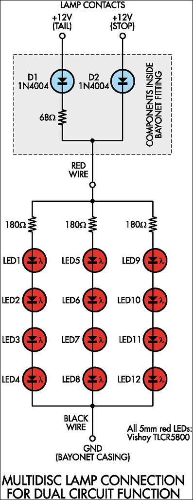
Before proceeding with the implementation, it is important to ensure that the output brightness is adequate for a stop and tail-light application. The light output may vary based on the tail-light lens and reflector assembly, so caution should be...
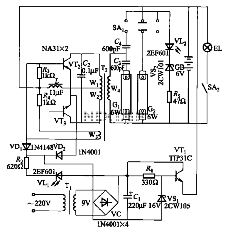
This is a Nissan Panasonic rechargeable emergency fluorescent lamp circuit. It features built-in 6V, 4Ah high-energy batteries that can be directly charged. The circuit supports two 6W fluorescent lamps. It includes functional switches SAi and SAz. When SAi is...
Although modern electrical appliances are increasingly self-powered, particularly portable devices used during camping or summer vacations, there are still occasions when a 230 V AC source is necessary. Additionally, it is beneficial for this source to operate at a...
The headlamp schematic for the Daewoo Korando is illustrated in the accompanying figure. It details the connections and wiring between various components of the vehicle's headlamp system, including the alternator, ignition switch, buy-off switch, high lamp relay, low lamp...
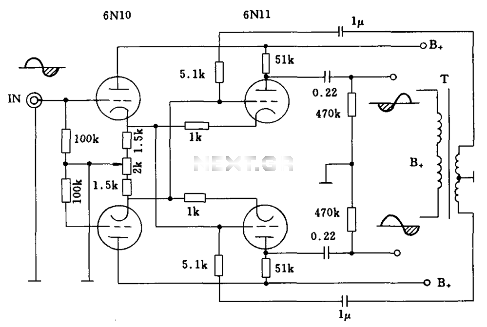
Balanced cross tube inverter circuit, also known as the Chelles inverter circuit, can be utilized as a preamplifier and employs 6N10 and 611 tubes in an inverted configuration. The circuit is designed to work with a final amplifier tube, specifically...