
Dark Activated Terrace Lamp

The circuit is designed to automate lighting control based on ambient light conditions, specifically transitioning lamps to an 'on' state at sunset and returning them to an 'off' state at dawn. The integration of this circuit with existing switch configurations allows for straightforward installation without the need for extensive rewiring.
The core functionality is typically achieved using a light-dependent resistor (LDR) or a phototransistor, which senses the ambient light levels. When the light level drops below a predetermined threshold (indicating sunset), the circuit activates Q1, which in turn allows current to flow to the connected lamps, illuminating them. Conversely, when the light level rises above the threshold (indicating dawn), Q2 is activated, interrupting the current flow and turning off the lamps.
The compact design of the circuit ensures that it can be easily accommodated within the existing switch enclosures, maintaining aesthetic integrity while enhancing functionality. Additionally, the parallel wiring configuration allows the user to retain manual control via the existing switches while benefiting from the automatic lighting feature.
In summary, this circuit serves as an efficient and user-friendly solution for automating outdoor or indoor lighting systems, providing convenience and energy savings by ensuring lights are only on when necessary.Compact circuit, Can be wired in parallel to existing switches This device allows one or more lamps to illuminate at sunset and turn off at dawn.Q1 and Q2.. 🔗 External reference
Related Circuits
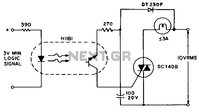
A simple solid-state relay circuit drives the 10-Vac telephone indicator lamps from logic circuitry while maintaining complete isolation between the 10-V line and the logic circuit. The described circuit utilizes a solid-state relay (SSR) to control 10-Vac telephone indicator lamps...
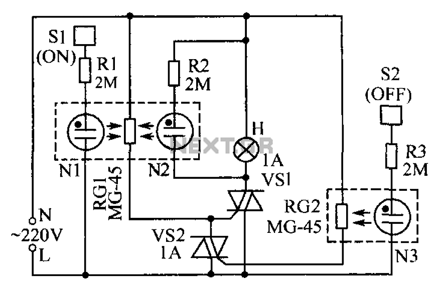
The circuit operates based on the principle that neon tubes N1, N2, and the photosensitive resistor RG1 form an optocoupler. When a finger touches the metal sheet S1, N1 lights up, causing RG1's resistance to decrease. This reduction allows...
This simple circuit, as shown in the schematic diagram, activates a switch using sound. It can be utilized for various applications, such as automatic sound-controlled disco lights or a car's LED light show. The transistor Q1 amplifies the audio...
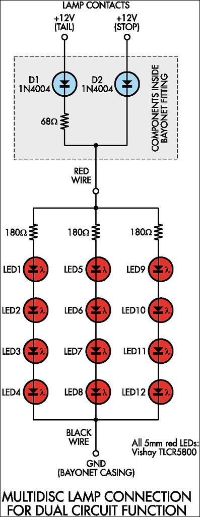
Before proceeding with the implementation, it is important to ensure that the output brightness is adequate for a stop and tail-light application. The light output may vary based on the tail-light lens and reflector assembly, so caution should be...
The circuit operates similarly to the original strobes, but utilizes a glowing tube. The glowing tube remains constant, with the two electrodes continuously supplied with electricity. This current activates the two resistance components of the glow tube, causing mercury...
For several years, a rear fog lamp has been mandatory for trailers and caravans to enhance visibility in foggy conditions. When the fog lamp is activated, the fog lamp of the towing vehicle must be turned off to prevent...