
LED Lighting For Dual-Filament Lamps

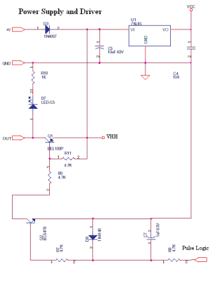
The circuit design includes a dual-function LED assembly intended for use in automotive lighting applications, specifically for stop and tail lights. The configuration involves two primary diodes, D1 and D2, which are integral to managing the light output based on the operational mode of the lamp. The resistor, rated at 68Ω, serves to limit the current when the tail light is activated, ensuring that the LED operates within safe parameters to prevent overheating and premature failure.
When the vehicle's brake is engaged, the circuit transitions to the stop mode. In this mode, D2 becomes forward-biased, effectively bypassing the resistor and allowing for increased current flow to the LED. This results in a brighter output, which is essential for safety, as it alerts following drivers of the vehicle's deceleration.
The assembly process requires meticulous attention to detail. The components must be securely soldered within the copper tube, ensuring that there are no loose connections that could lead to failure. The use of heat shrink tubing is critical for insulation, as it prevents short circuits that could arise from exposed connections. The soldering of the anode leads directly to the contacts on the base is a crucial step, as it establishes the electrical connection necessary for the diodes to function correctly.
Testing the lamp prior to final assembly is strongly recommended. This allows for verification of the light output and ensures that the transitions between tail and stop modes are functioning as intended. If the desired brightness levels are not achieved, the value of the additional resistor can be adjusted to fine-tune the current flow, thereby optimizing the LED performance for both operational modes.
Overall, this circuit design emphasizes safety and functionality, making it suitable for automotive applications where visibility is paramount. Proper assembly and testing will ensure reliable operation, contributing to the overall effectiveness of the vehicle's lighting system.Before we describe how it`s done, note that we recommend that the result be checked as having sufficient brightness for a stop & tail-light application. That`s because the light output may be inadequate, depending on the tail-light lens and reflector assembly - so use any modified lamps with discretion!
As shown, an additional diode (D1) and resis tor (68W) provide power from the "tail" circuit. Alternatively, when the "stop" circuit is powered, the resistor is bypassed by D2, thus increasing the LED current and the light output. After soldering in the copper tube but before soldering the platform board to the bayonet lamp base, the three components inside the dotted box must be wired up inside the base.
The anode leads of the diodes can be soldered directly into the contacts ("bumps") on the base (a fine file or glass paper may be needed to get a nice round shape). Everything must be insulated (use heatshrink tubing). The red wire from the Multidisc board is then soldered to the junction of D2 and the resistor. The black wire is soldered directly the metal casing of the lamp. We suggest testing the lamp before soldering the platform board in place. It may be necessary to vary the value of the additional resistor to get the correct intensity change between stop & tail modes.
🔗 External reference
Related Circuits
This month's project is based on the 4017 chip that was used in a previous project. It is advisable to review the fundamentals of the 4017 chip as presented in last month's project. The circuit has been modified slightly;...
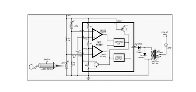
This circuit is designed around a 555 timer and utilizes a minimal number of components. Due to its simplicity, it can be easily constructed and operated by beginners. The circuit leverages the 555 timer IC, which is a versatile and...
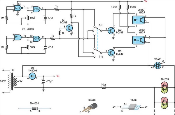
This circuit utilizes low-voltage AC to power a string of approximately 50 bi-color LEDs, with two LEDs connected in inverse parallel. The power supplied to the LEDs is managed by a Triac and two optocouplers, whose phototransistors are also...
If you have ever attempted to dim an LED using a simple potentiometer, it is recognized that this method is not very effective. Similar to standard diodes, the voltage-current characteristic of LEDs is non-linear. Consequently, depending on the potentiometer...
The control voltage is fed into the first half of a 1458 op-amp, this stage inverts the signal and sets the offset and gain for the right channel gain control circuit. This signal is then fed into the second...
This circuit is a digital panel meter (DPM) featuring an analog bar graph display and a 3.5-digit digital display. The ICL7107 is configured for 200mV input. The U4A operational amplifier (LF353) amplifies the 200mV full-scale input to the required...