
Dark and Light Activated Relay circuit diagram

The circuit described involves a potentiometer that functions as a variable resistor, allowing for the adjustment of the trigger level in the circuit. This adjustment is crucial for fine-tuning the operation of the relay, ensuring that it activates at the desired threshold. The choice of diode is essential for reliable circuit performance; while the 1N914 is adequate for low-power applications, it is recommended to utilize a 1N4001 or a more robust diode to handle higher currents and reverse voltage spikes, thus ensuring the longevity and reliability of the circuit.
The 2N2222 transistor, known for its versatility in switching applications, can be replaced with several compatible alternatives such as NTE123A, ECG123A, and PN100. These substitutes provide similar characteristics in terms of current gain and switching speed, making them suitable for use in this circuit.
When designing the schematic, it is important to ensure that the connections between the potentiometer, diode, and transistor are clearly outlined. The potentiometer should be connected in such a way that it adjusts the voltage at the base of the transistor, which controls the relay operation. The diode should be placed in parallel with the relay coil to prevent back EMF from damaging the transistor when the relay is de-energized. Proper orientation of the diode is critical, with the anode connected to the ground side of the relay coil and the cathode connected to the supply voltage.
In summary, the circuit design must incorporate a potentiometer for trigger adjustment, a suitable diode for protection, and a reliable transistor for switching, ensuring that all components are compatible and correctly configured for optimal performance.The potensiometer adjust the trigger on` level. The diode in the circuit diagram shows to be 1N914. This is ok if you have a light-duty relay, also the 1N914 is a signal diode so actually does not qualify. Use a 1N4001 (or better) instead. A couple of substitutes for the 2N2222 transistor are: NTE123A, ECG123A, PN100, etc. We aim to transmit more information by carrying articles. Please send us an E-mail to wanghuali@hqew. net within 15 days if we are involved in the problems of article content, copyright or other problems. We will delete it soon. 🔗 External reference
Related Circuits
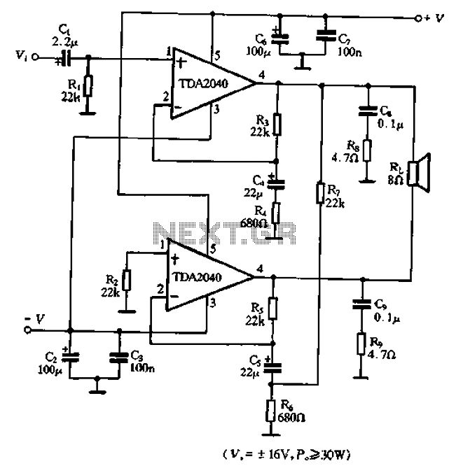
The TDA2040 is a power audio amplifier with a wider operating voltage range compared to the TDA2030, ranging from 4V to 20V. It can deliver an output power of 18W at a load of 4 ohms when supplied with...
The basic circuit illuminates up to ten LEDs in sequence, following the rhythm of music or speech picked up by a small microphone. The expanded version can drive up to ten strips, formed by up to five LEDs each,...
Zilog's Z8 Encore XP F1680 Series features a highly optimized set of capabilities specifically designed for stepper motor microstepping control. Key features of the Z8 Encore! XP F1680 include: an 11 MHz internal oscillator, two analog comparators, a 10-bit...
This section describes the components of the receiver, which includes the post-mixer amplifier, variable crystal filter, intermediate frequency (IF) amplifier, product detector, local oscillator, receiver muting, and audio amplifier. The transmit section features the local oscillator, transmit single balanced...
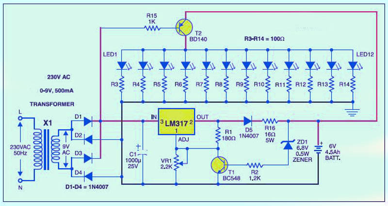
This is a low-cost circuit diagram for an emergency light utilizing a white LED. Components include an LM317 IC, a resistor, a transformer, an LED, and a variable resistor. The emergency light circuit using a white LED is designed for...
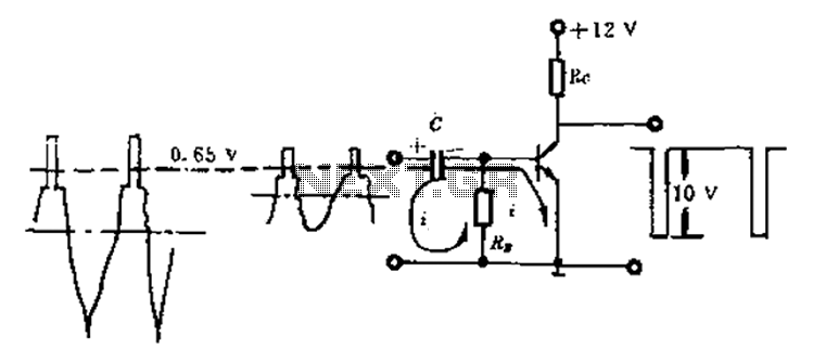
Amplitude separation circuit. A typical amplitude separating circuit is composed of a transistor, capacitance C, and resistances RB and RC. The input signal is a composite video signal, typically with a peak-to-peak voltage of about 2V. The output signal...