
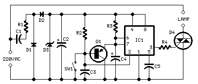
Low Cost Automatic LED Emergency Light

The emergency light circuit using a white LED is designed for efficiency and cost-effectiveness. The core component, the LM317 integrated circuit, serves as a voltage regulator that ensures the LED receives a stable voltage for optimal performance. The circuit typically operates from a transformer that converts the mains voltage to a lower AC voltage, which is then rectified to DC using a diode bridge.
The LM317 requires a minimum input-output voltage difference to function correctly, making it suitable for applications where the input voltage can vary. The output voltage can be adjusted using a variable resistor (potentiometer) connected to the adjustment pin of the LM317, allowing for fine-tuning of the LED brightness.
The resistor in the circuit is essential for current limiting, preventing the LED from drawing excessive current that could lead to overheating and failure. The value of the resistor is chosen based on the LED specifications and the desired current flow.
In summary, this low-cost emergency light circuit is efficient, utilizing commonly available components to provide reliable illumination during power outages or emergencies. The design emphasizes simplicity and functionality, making it an excellent choice for DIY enthusiasts and practical applications.This is a low cost circuit diagram for the emergency light based on white LED. Component: LM317 IC, Resistor, Transformer, LED, Variable .. 🔗 External reference
Related Circuits
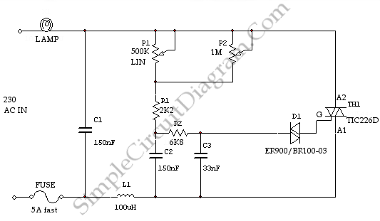
This is a light dimmer circuit. It does not include any special features and is a typical TRIAC-based dimmer circuit. This circuit is designed to operate with... A TRIAC-based light dimmer circuit is a common electronic design used to control...
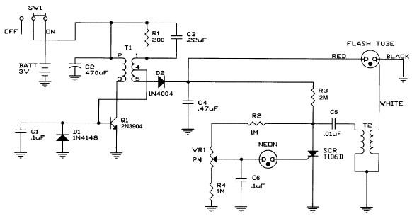
Caution! This strobe light circuit operates on 220V, making measurements and experiments extremely hazardous, even after disconnecting it from the mains. The strobe light circuit is designed to produce high-intensity flashes of light at specified intervals. It typically consists...
This circuit is intended to let the user turn off a lamp by means of a switch placed far from bed, allowing him enough time to lie down before the lamp really switches off. 15 seconds delayed switch-off. A...
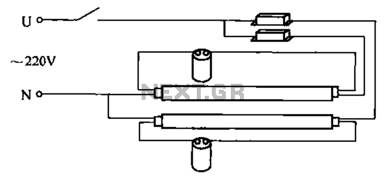
A double tube fluorescent lighting circuit is illustrated. In certain situations, a single tube light may not fulfill the lighting requirements, necessitating the use of double tube lighting. The physical installation is depicted in the circuit of a double...

This slideshow is based on the LED Design Ideas Collection, which features a compilation of LED-related circuits and design applications submitted by readers and published in EDN's Design Ideas section. Users can browse through the circuit schematics in this...
Controlled rectifiers are line-commutated AC to DC power converters that convert a fixed voltage and fixed frequency AC power supply into a variable DC output voltage. The input supply provided to a controlled rectifier is an AC supply with...