
Dark detector circuit

The dark detector circuit employs the NE555 timer IC in its astable or monostable mode, depending on the desired application. The LDR serves as the primary sensing element, and its resistance varies inversely with the amount of light falling on it. This property allows the circuit to detect the transition from light to dark effectively.
In operation, when light levels drop below a predefined threshold, the LDR's resistance increases, causing a change in voltage at the input of the NE555. This change is detected by the timer, which then triggers the output pin (pin 3) to go high, activating the connected buzzer. The buzzer emits a sound, alerting occupants of the change in light conditions.
For applications requiring the control of electrical devices, a transistor can be used to amplify the signal from the NE555 output. This transistor can drive a relay, allowing for the switching on or off of various appliances based on the light detected by the LDR. The circuit can be further enhanced by incorporating adjustable resistors or potentiometers to fine-tune the sensitivity of the LDR, enabling customized operation based on specific lighting conditions.
The overall design is straightforward and can be implemented on a breadboard for prototyping or on a printed circuit board (PCB) for permanent installations. Proper power supply decoupling and component selection, including the buzzer type and relay specifications, are essential for ensuring reliable circuit performance.The dark detector circuit shown here can be used to produce an audible alarm when the light inside a room goes OFF. The circuit is build around timer IC NE555. A general purpose LDR is used for sensing the light. When proper light is falling on the LDR its resistance is very low. When there is no light the LDR resistance increases. At this time th e IC is triggered and drives the buzzer to produce an alarm sound. If a transistor and relay is connected at the output (pin3) of IC1 instead of the buzzer, electrical appliances can be switched according to the light. 🔗 External reference
Related Circuits
The circuit on this page is for a simple light detector circuit board that has 8 detectors that can be used with visible or infrared light systems. The detectors use LM339 voltage comparators as the active element. Phototransistors or...
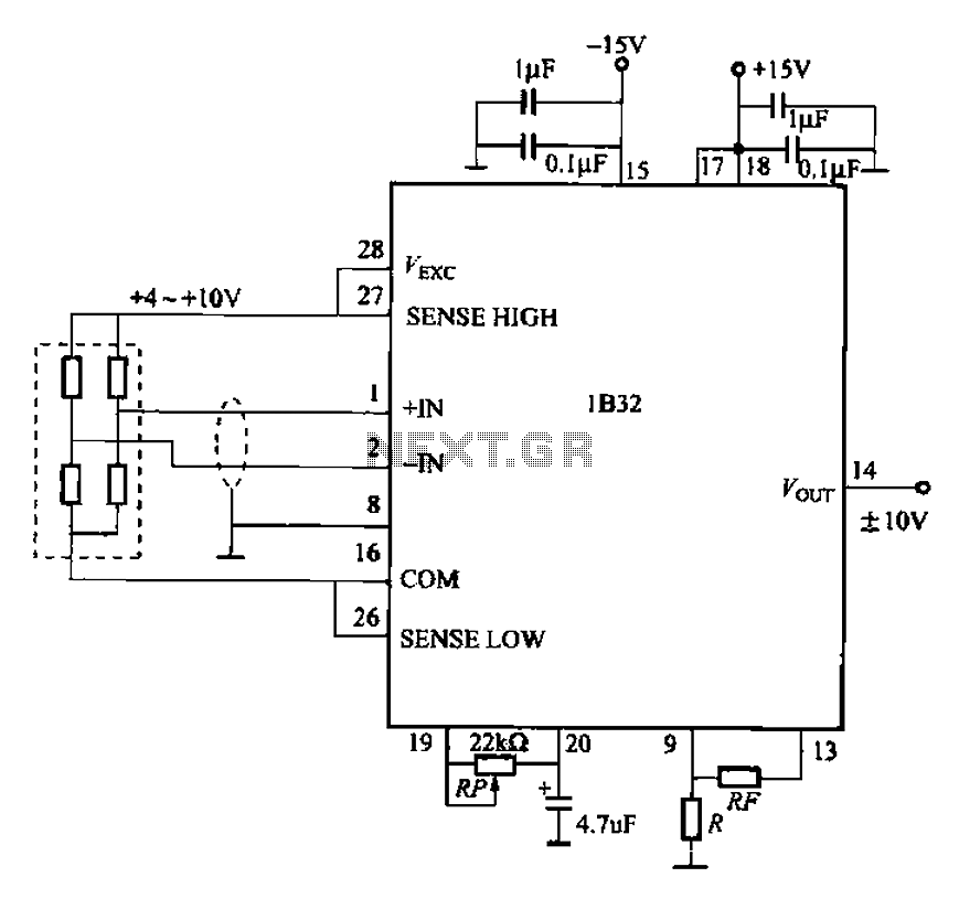
The circuit for bridge measurements is straightforward, as illustrated in the figure. The sensor bridge drive voltage can be adjusted between +4V and +10V, depending on the specific requirements of the sensor. Two fixed gain options of 333.3 and...

The detector is designed to sense and signal to another circuit when an appliance is connected to the mains voltage. For this purpose, an optocoupler, IC1, is utilized. The circuit employs an optocoupler (IC1) to provide electrical isolation between the...
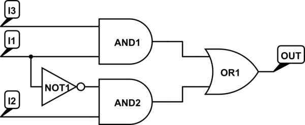
There are integrated circuits that contain AND, OR, and NOT gates. The inquiry revolves around the existence of a single chip that encompasses all the required logic gates. If such a chip does not exist, specific alternatives should be...
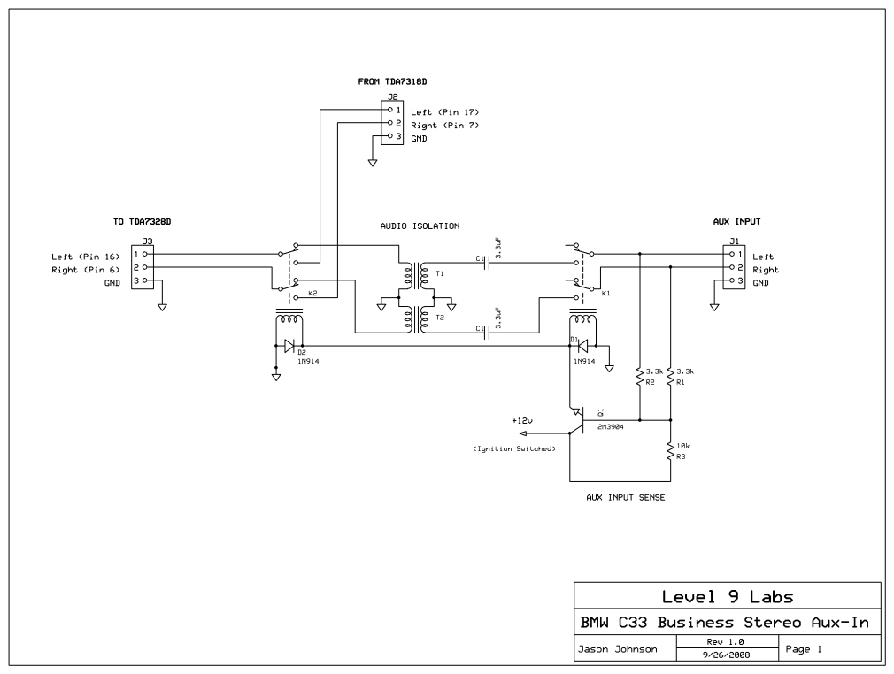
The layout of the PC board led to the decision to insert a stereo 3mm canceling type jack (5 pin) at the volume control chip inputs, which was mounted on the front panel. A suitable jack was not available...
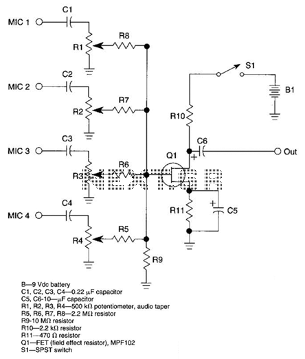
A JFET transistor is utilized as a high-to-low impedance converter and signal mixer. The input impedance is approximately 50.0 kΩ, which can be increased by adjusting resistors R5 to R8 up to 10 MΩ. The output impedance is around...