
Constant Voltage measuring circuit

The described circuit operates as a bridge measurement system, utilizing a sensor bridge configuration to convert physical parameters into electrical signals. The adjustment of the sensor bridge drive voltage between +4V and +10V allows for flexibility in accommodating various sensor types and their specific output characteristics. This range ensures that the sensor operates within its optimal range for accurate readings.
The circuit includes two fixed gain settings of 333.3 and 500, which are crucial for amplifying the sensor's output signal. The choice of gain is determined by the application requirements, allowing for precise adjustments based on the sensor's characteristics. The active low output configuration indicates that the output signal will be low when the input exceeds a certain threshold, which is often useful in digital interfacing scenarios.
Moreover, the circuit supports continuous gain adjustment from 100 to 5000 by varying the RF/R ratio. This feature is particularly advantageous in applications requiring dynamic signal amplification, enabling the system to adapt to different measurement conditions or sensor outputs. The output voltage of 10V provides a robust signal that can be easily interfaced with subsequent processing stages, such as analog-to-digital converters or microcontrollers.
Overall, this bridge measurement circuit is designed to provide a reliable and flexible solution for various sensor applications, ensuring accurate signal processing and adaptability to different operational requirements.1832 for bridge measurements, the external circuit is very simple, as shown in FIG. Belly adjust sensor bridge drive voltage ( feet), the adjustment range is +4 a + 10V, based on the sensor to determine the specific value of the actual need. Two fixed gain 333.3,500 pin ?, ? then active low, from 100 to 5000 continuous gain adjustment is determined by the a, foot RF/R. Output voltage is 10V.
Related Circuits

A light dimmer is quite uncommon in a caravan or on a boat. This document outlines how to create one, allowing for mood adjustment when needed. A light dimmer circuit is an essential component for enhancing the ambiance in confined...
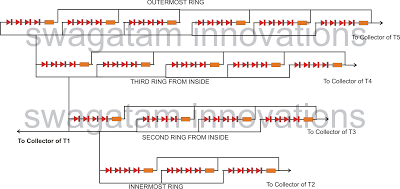
The following article outlines a sophisticated LED sequencing and diverging ring light that can serve as a tail brake light in vehicles. This circuit concept was proposed by a dedicated reader, Mr. Bobby. The design aims to create a...
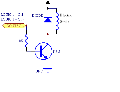
A fingerprint door lock system is being considered for implementation. The primary component is a fingerprint reader that, upon recognizing a valid fingerprint, will instruct an Arduino microcontroller to activate a locking mechanism for a predetermined duration. The locking...
This project is designed to enhance security for personal belongings left unattended on a beach towel, in an office, or workshop setting. It utilizes a compact circuit powered by standard primary cells or rechargeable batteries to generate a low-energy,...

Using only a single transistor and a few passive components, a fairly sensitive peak detector circuit can be built. This peak detector circuit is suitable for various applications. The peak detector circuit utilizes a single transistor, typically configured in a...
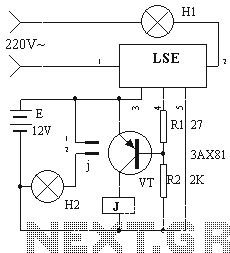
The device circuit operates as illustrated in Figure 11. Power outages are a common occurrence, but in certain situations, maintaining power is critical, such as during ongoing surgeries. The circuit employs a simple design that is fully automated. When...