
darkness activated alarm

The circuit operates on the principle of detecting changes in light intensity using an LDR, which is a variable resistor that decreases its resistance when exposed to light. In this configuration, the LDR is positioned in such a way that it remains in darkness when the area is unoccupied. The 555 timer, configured as a monostable multivibrator, is triggered when the LDR's resistance is sufficiently high, pulling the voltage at pin 2 low. This low voltage activates the timer, which then outputs a high signal at pin 3 for a predetermined duration, set by the values of R2 and C1.
The timing components, R2 and C1, are crucial for determining how long the buzzer will sound after the alarm is triggered. By selecting appropriate values for these components, one can adjust the duration of the alarm to suit specific requirements. The piezo buzzer, which operates at 6 volts, produces an audible sound when activated, alerting occupants of the presence of an intruder or unexpected movement.
The adjustable preset resistor P1 allows for fine-tuning of the circuit's sensitivity to ambient light conditions. This feature ensures that the alarm will only activate in low-light situations, preventing false alarms during the day or in well-lit environments. Installation on a wall is straightforward, and the compact nature of the circuit allows for easy integration into home security systems.
Overall, this circuit provides an efficient and economical solution for creating a darkness-activated alarm system, leveraging the reliability of the 555 timer and the simplicity of passive components. Proper calibration and placement will enhance its effectiveness in detecting motion in dimly lit areas.Most darkness activated alarms employ opamps and some logic ICs. Here, a less expensive approach is shown based on the eternal 555, this time in monostable multivibrator mode. Components R2 and C1 represent a one-second network. When the LDR (light dependent resistor) is in the dark, its resistance is high, pulling pin 2 of the 555 to ground.
This triggers the monostable and the (active!) 6-volt piezo buzzer will sound. Preset P1 is adjusted depending on ambient light levels. The circuit may be fitted on a wall in your home. Assuming P1 has been set for the existing ambient light level, the shadow cast by anybody entering the room or hallway will trigger the alarm. 🔗 External reference
Related Circuits

This circuit is a laser alarm system similar to those depicted in various movies. It employs a laser pointer beam to secure valuables and property. When the beam is interrupted by a person, animal, or object, the resistance of...
The integrated circuit (IC) is a quad 2-input "AND" gate, specifically a CMOS 4081. These gates output a HIGH signal only when both inputs are HIGH. When the key connected to pin E is pressed, current flows through resistor...
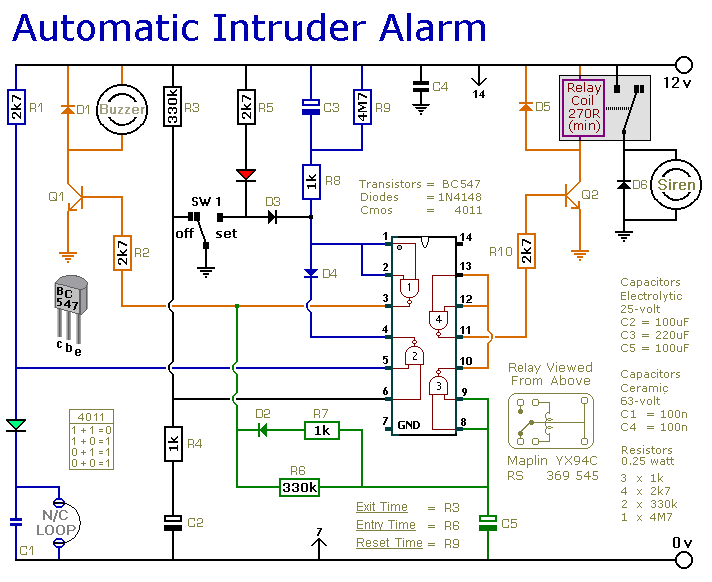
This is a simple single-zone home alarm system circuit. Its features include entry delays, a timed siren cut-off, and automatic exit. It is designed to be used with the usual types of normally-closed input devices such as foil tape,...

This circuit has been designed to alert the vehicle driver that he has reached the maximum fixed speed limit (i.e. in a motorway). It eliminates the necessity of looking at the tachometer and to be distracted from driving. There...
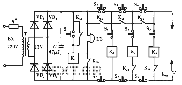
The circuit operates as illustrated in Figure 5-2a. It includes an alarm switch (S). When switch S is pressed, relay K is activated, which closes two normally open contacts. This action triggers the alarm bells. The alarm continues to...

This is a simple power resumption alarm circuit that can be installed within the switch box. It emits beeping sounds when power is restored following a power outage. The power resumption alarm circuit serves as a practical solution for alerting...