
Laser Alarm

This laser alarm system is designed to provide a reliable and effective means of securing areas or valuables. The use of the TL072 operational amplifier as a voltage comparator allows for precise detection of interruptions in the laser beam, ensuring that the system is responsive to potential intruders. The adjustable voltage divider enables customization of the sensitivity of the alarm system, allowing users to tailor the operation to their specific needs.
The choice of components, including the photodiode and resistors, is critical for achieving the desired response time and sensitivity. The addition of hysteresis via resistor R2 is particularly important in reducing false alarms caused by minor fluctuations in light levels, enhancing the overall reliability of the system. Capacitor C1 plays a dual role in stabilizing the circuit and filtering out brief interruptions, making the system robust against momentary disturbances.
The physical configuration of the system, including the placement of mirrors, is essential for directing the laser beam effectively. This design consideration ensures that the alarm covers the intended area while minimizing the chance of accidental activation. The use of a black box with a narrow opening not only protects the components but also enhances the system's stealth, making it less detectable to potential intruders.
In summary, this laser alarm system exemplifies a practical application of optical sensors and electronic components to create a security solution that is both effective and customizable. Proper assembly and configuration are crucial for optimal performance, ensuring that the system remains functional under various environmental conditions.This circuit is a laser alarm system like the one we see in various movies. It uses a laser pointer beam to secure your valuables and property. Essentially, when the beam gets interrupted by a person, animal or object, the resistance of a photodiode will increase and an alarm will be activated. The laser and the receiver can be fitted in same box, sharing a common power supply. As the receiver draws less than 10 mA on average, you`ll soon find that the laser is the most current hungry device! Mirrors are used to direct the beam in whatever setup you require. Examples of a passage and an area protected by the alarm are shown in the diagram. In the circuit diagram we find a TL072 op-amp (IC1. A) configured as voltage comparator between the voltage reference provided by the adjustable voltage divider P1/R4 and the light-dependent voltage provided by the voltage divider consisting of photodiode D1 and fixed resistor R3.
When the laser beam is interrupted, the voltage on comparator pin 2 drops below that at pin 3, causing the output to swing to (almost) the positive supply voltage and indicating an alarm condition. This signal can drive a siren, a computer or a light that hopefully will deter the intruder. Alternatively it can be used to silently` trigger a more sophisticated alarm. Resistor R2 provides some hysteresis to prevent oscillation when the two comparator input voltages are almost equal.
Capacitor C1 makes the circuit immune to short, accidental interruptions of the beam, e. g. , by flying insects. If you want your circuit to have faster responses you can reduce its value to 1 µF. The operation of the circuit is illustrated by the waveform diagram, which also proves the hysteresis action that sets an upper and a lower threshold on the input voltage. You can also see the delay introduced by capacitor C1. The circuit is simple and could be assembled on a piece of breadboard. After assembling the circuit and testing it, you should mount it in a black box that has just a small hole.
You may decide to put the laser in the same box but only if you are sure there is no way the photodiode can see` the laser beam directly. The small hole should be filled with a black drinking straw so that only light from the direction of the laser beam can enter.
With the appropriate setup of the box and the mirrors, the laser beam is so intense that even direct sunlight cannot affect the operation of the photodiode. 🔗 External reference
Related Circuits
This is a fire alarm system utilizing the IC TD2002 suite to detect fire incidents. The alarm is crucial in residential complexes, allowing for early detection. It operates by detecting fog generated by fire, which reduces the light reaching...

This car alarm circuit features an 18-second delay for both entrance and exit. It sounds continuously for 6 minutes before automatically turning off the horn and preparing for the next triggering event. The alarm remains activated even if the...
To increase the chances of observing the northern lights, the limitations of current aurora prediction methods can be circumvented by directly sensing the light emitted by the aurora. The Aurora Alarm is a device designed to achieve this goal...
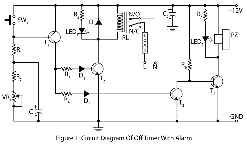
An off timer with an alarm is a straightforward project designed to indicate the end of a specified time period. The circuit utilizes four transistors. It includes a circuit diagram along with a parts list and a description of...
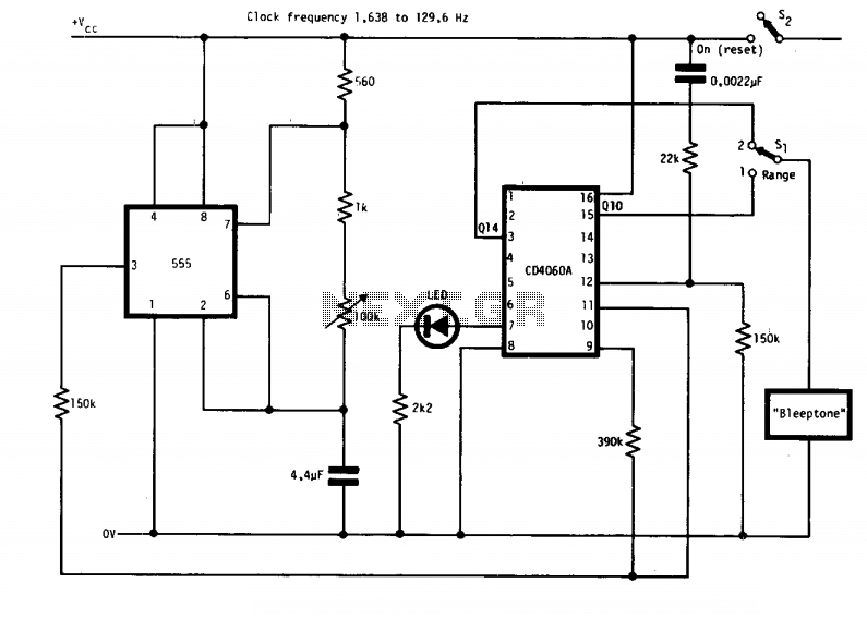
The circuit features two timing ranges: from 10 seconds to 5 minutes and from 1 minute to 80 minutes. It is powered by a 9-V battery. An LED is connected in a manner that allows for a consistent flashing...

The door alarm is designed to be mounted on the door handle and emits a beep when someone touches the door handle from the outside. The door alarm circuit operates on the principle of detecting physical contact with the...