
Darkroom time exposure of the second circuit

The described circuit employs a 555 timer IC configured in monostable mode to create a time delay for exposure in a darkroom setting. The 555 timer generates a pulse output upon receiving a trigger signal, which initiates the timing cycle. The relay, activated by the output of the 555 timer, controls the power to the exposure light source, ensuring that the light is turned on for the duration specified by the timing circuit.
Potentiometer RP serves as the primary means for adjusting the exposure time. Its resistance value directly affects the time constant of the timing circuit, which is determined by the formula T = 1.1 * R * C, where T is the time in seconds, R is the resistance in ohms, and C is the capacitance in farads. By varying the resistance of RP, the exposure time can be finely tuned between 1 second and 120 seconds.
For applications requiring longer exposure times beyond the standard range, the circuit can be modified by increasing the capacitance of capacitor C4. This adjustment increases the time constant of the circuit, thereby extending the maximum exposure time. It is essential to ensure that the relay used can handle the power requirements of the exposure light source and that the components are rated appropriately for the voltages and currents involved in the circuit.
Overall, this darkroom exposure control circuit provides a flexible and efficient solution for managing light exposure times, suitable for various photographic processes. Proper calibration of the potentiometer and capacitor will ensure optimal performance and reliability during operation.Darkroom time exposure of the second circuit It uses 555 IC A for the timing circuits. KA by the relay contacts to the control system of the exposure light source. Adjustment p otentiometer RP, exposure time can be varied within the scope of 1-120s. For more long delay, may increase the capacity of the capacitor C4.
Related Circuits
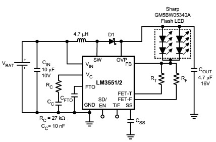
The LM3551 and LM3552 are fixed frequency, current mode step-up DC-DC converters featuring two integrated NFETs. These devices facilitate the design of a straightforward and highly precise LED brightness control system. They are capable of driving loads up to...
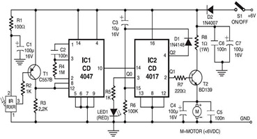
The following circuit illustrates an Infrared Toy Car Motor Controller Circuit Diagram. This circuit is based on the 4017 IC. Features: operating at .. The Infrared Toy Car Motor Controller Circuit utilizes a 4017 Decade Counter IC, which is integral...
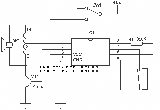
The alarm circuit operates as follows: When the power switch SW1 is turned on, the alarm system becomes active. If a magnet is brought close to the spring, the magnetic field attracts the spring, causing the dynamic and static...
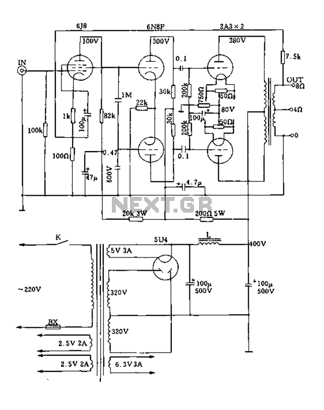
FIG. 2A3A is a low direct thermal resistance transistor with a resistance of only 800 ohms. The output transformer has a primary screen to load impedance of 3.5k ohms. The push-pull amplifier tube operates with a screen voltage ranging...
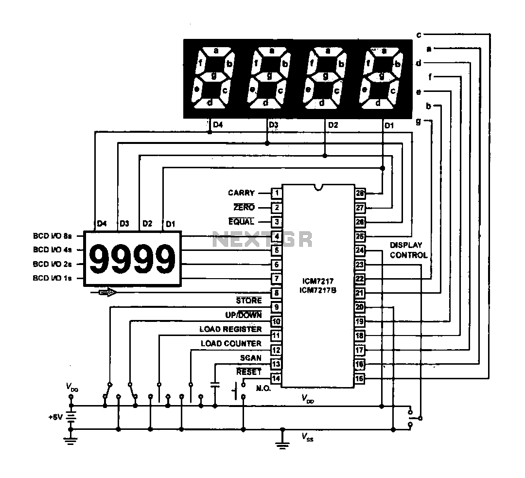
The circuit drives the light-emitting diode in a digital display configuration. The count signal is fed into the ICM7217 chip, which processes the count and subsequently drives the digital display board. The connection between the thumbwheel switches is illustrated...
An increasing number of appliances draw a very small current from the power supply. If designing a mains-powered device, one can generally choose between a linear and a switch-mode power supply. However, when the appliance's total power consumption is...