
Infrared Toy Car Motor ControllerCircuit Based On The 4017IC

The Infrared Toy Car Motor Controller Circuit utilizes a 4017 Decade Counter IC, which is integral in controlling the operation of the toy car's motors based on infrared signals. The circuit is designed to interpret signals received from an infrared remote control, enabling the toy car to move forward, backward, or turn based on the commands sent from the remote.
The circuit typically includes an infrared receiver module connected to the input of the 4017 IC. When the infrared signals are detected, the 4017 IC counts the pulses and activates the output pins in sequence. Each output pin corresponds to a specific action for the toy car, such as moving forward or turning. The outputs of the 4017 are connected to motor driver circuits, which can handle the higher current requirements of the motors.
Additional components in the circuit may include resistors for current limiting, capacitors for noise filtering, and diodes for protection against back EMF generated by the motors. The design should ensure that the power supply is adequate for the motors, typically requiring a separate battery pack to prevent voltage drops that could affect the performance of the infrared receiver.
Overall, this circuit exemplifies a simple yet effective method to control a toy car's movements using infrared technology, leveraging the capabilities of the 4017 IC for sequential output control.The following circuit shows about Infrared Toy Car Motor Controller Circuit Diagram. This circuit based on the 4017IC. Features: operating at .. 🔗 External reference
Related Circuits
The objective is to operate a motor using an L293D Motor Drive Shield, which can handle 600mA per coil. The motor consumes 400mA per coil, suggesting compatibility. However, the datasheet does not clearly indicate the pinouts, only labeling them...
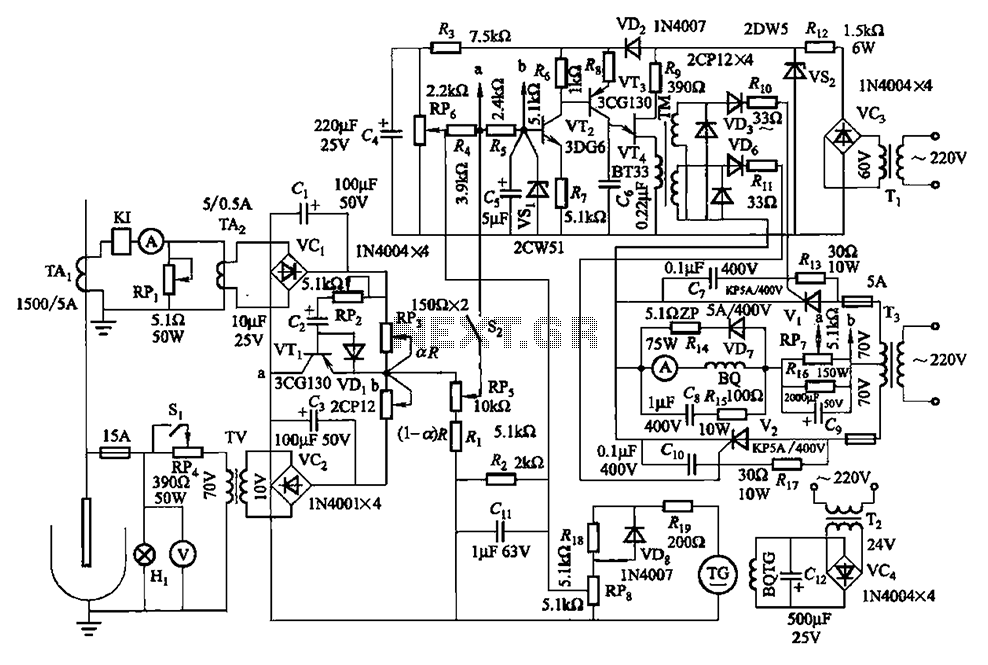
The circuit is illustrated in Figures 16-95 to 16-97. The electrode automatic adjuster demonstrates enhanced performance, featuring a high-accuracy, well-linear current output type bridge. Additionally, it incorporates a differential arc current negative feedback circuit (advanced) that allows for preemptive...
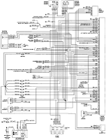
The electrical wiring diagram for the 1993 VW Passat includes the Engine Control Module, Automatic Control Unit, and Automatic Solenoid. This diagram illustrates the connections and wiring between various components of the vehicle's system, such as the multi-function switch,...
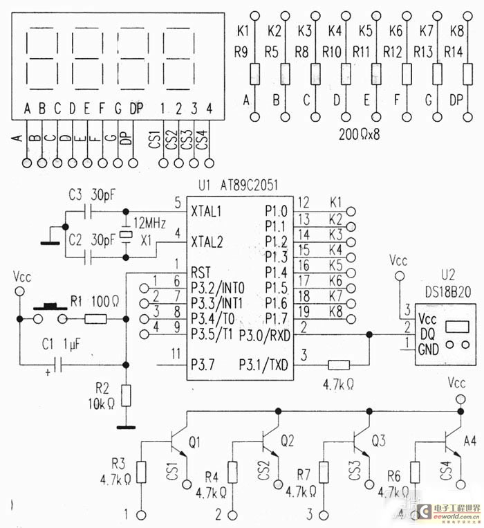
This project utilizes a USB port for power supply, employs a DS18B20 temperature sensor for data acquisition, and is controlled by an AT89C2051 microcontroller. A common anode quad-digit seven-segment display is used for output, allowing for temperature measurement visualization....
The following circuit illustrates a Plant Moisture Meter Circuit Diagram. This circuit is based on the LM741 integrated circuit (IC). Features include a meter that indicates moisture levels. The Plant Moisture Meter Circuit utilizes the LM741 operational amplifier to measure...
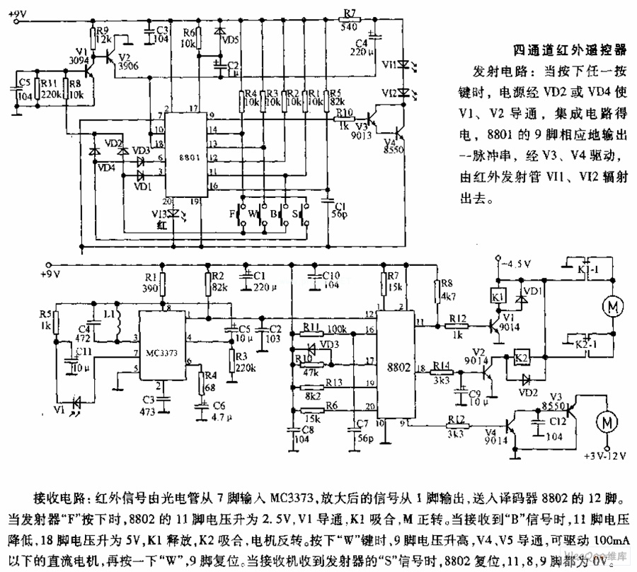
The receiving circuit involves an infrared signal being input to the MC3373 from pin 7 via a phototube. The amplified signal is output from pin 1 and sent to pin 12 of the decoder 8802. When the transmitter F...