
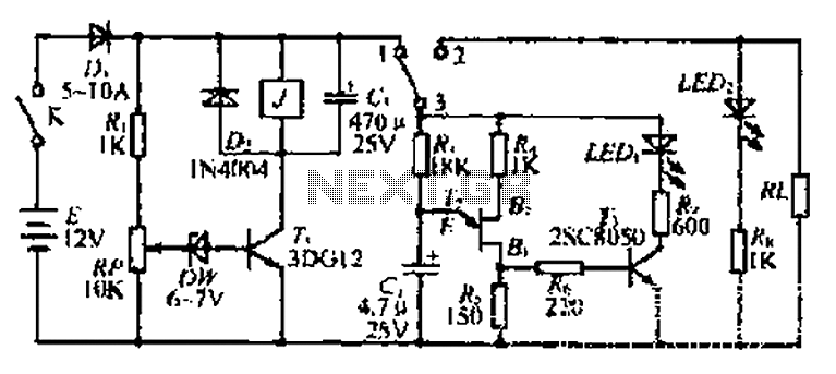
Darlington phototransistor type light-triggered circuit diagram of a switching application

The described circuit leverages the high sensitivity of a Darlington phototransistor, which is capable of amplifying weak light signals significantly. The operational amplifier serves to further enhance the signal processing, enabling the circuit to detect and respond to minimal light levels effectively.
In the standard configuration, the phototransistor is positioned to receive light, with the output connected to the op-amp configured as a comparator. The reference voltage at the non-inverting input of the op-amp is set to a level that determines the threshold for switching. When the light intensity exceeds this threshold, the op-amp outputs a high signal, activating the connected load.
For applications requiring the circuit to trigger in the absence of light, modifications can be made. By swapping the positions of R1 and the photodiodes, the circuit can be inverted. Additionally, reversing the inputs of the op-amp will alter the behavior, allowing it to activate when the light level drops below a certain point, effectively creating a dark-triggered switch.
This flexibility makes the Darlington phototransistor switching circuit suitable for various applications, including automatic lighting systems, security alarms, and light-sensitive controls. The ability to fine-tune the sensitivity and response characteristics through component selection and configuration further enhances its versatility in electronic design.Darlington phototransistor type light-triggered switching circuit application As a result of the sub-type Darlington phototransistor and the op amp, so very faint light can fli p the circuit. When the position of R1 and photodiodes swap, or op amp inverting and non-inverting input reversed position, you can put this circuit modified to trigger the opening dark.
Related Circuits
This circuit is designed for children's entertainment and can be installed on bicycles, battery-powered cars, motorcycles, as well as on models and various games and toys. When switch SW1 is positioned as depicted in the circuit diagram, it generates...
Adjustable 1.5 - 35 V DC Regulated Power Supply Circuit Diagram. This diagram includes three circuit designs and is categorized under Power Supply. For more information, refer to the detailed post titled "Adjustable 1.5 - 35 V DC Regulated...
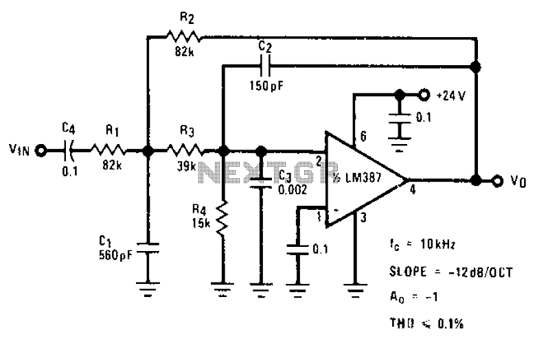
The circuit provides a passband gain of 1 with a corner frequency of 10 kHz, designed to eliminate high-frequency noise such as hiss, ticking, and popping sounds. This circuit operates as a low-pass filter, effectively attenuating frequencies above the specified...
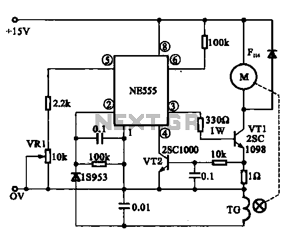
The Miniature DC Motor Speed Control circuit is designed to maintain a steady speed for micro motors, as illustrated in Figure 8-32. The circuit utilizes a voltage feedback mechanism suitable for applications such as tape recording machines that employ...
The discharge control circuit consists of a battery management system designed to prevent over-discharge of a battery. It features a relay control mechanism that activates when the battery voltage drops below a specified threshold of approximately 10.5V. The circuit...
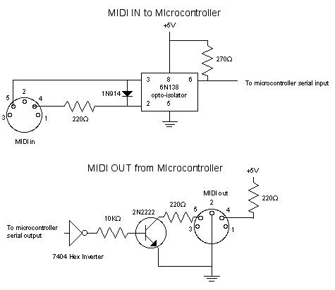
MIDI, or Musical Instrument Digital Interface, is a specification for a communications protocol between digital synthesizers and other digital music devices. It was developed to be as simple and general as possible, providing synthesizer manufacturers with significant flexibility while...