
Miniature DC Motor Speed Control circuit

The Miniature DC Motor Speed Control circuit operates by employing a combination of feedback mechanisms and control components to ensure consistent motor performance. The NE 555 timer serves as the central control unit, functioning in astable or monostable mode depending on the application requirements. In this configuration, the timer generates a series of pulses that dictate the switching of the transistor VT1, which in turn energizes the motor.
The feedback loop is critical for maintaining the desired speed. The voltage feedback from the motor is processed by the NE 555 timer, which compares the actual motor speed to the setpoint defined by the potentiometer VR1. By fine-tuning VR1, the user can adjust the threshold at which the NE 555 timer activates the transistor, thereby increasing or decreasing the motor speed as needed.
In the case of the speed feedback motor drive circuit depicted in Figure (b), the integration of a speed signal generator (TG) enhances the control mechanism. The TG outputs a signal that corresponds to the actual speed of the motor. This signal is rectified and converted to a DC voltage, which provides real-time feedback to the NE 555 timer. The timer continuously monitors this feedback and adjusts its output accordingly to ensure that the motor operates at a steady speed, compensating for any variations in load or supply voltage.
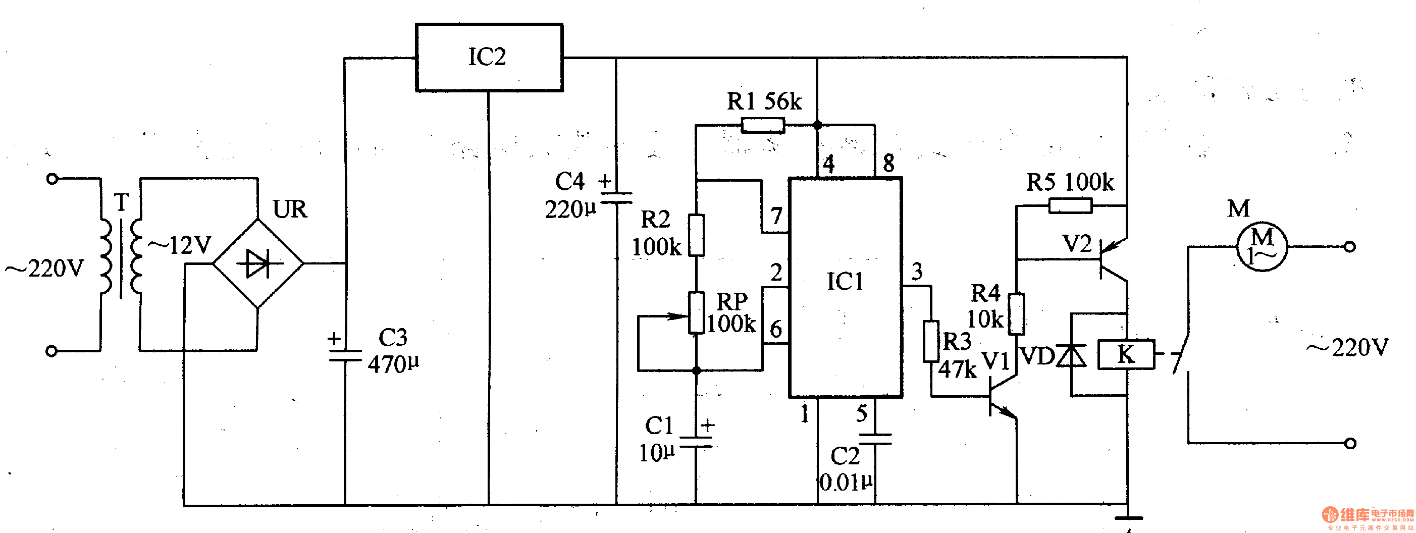
Overall, this circuit design is particularly useful in applications where precise speed control of miniature DC motors is essential, offering both simplicity and effectiveness in maintaining operational stability.Miniature DC Motor Speed Control circuit b Having a steady speed function micro motor drive circuit steady speed Miniature DC motor control circuit shown in Figure 8-32. Ring (a) shows the voltage feedback mode is for tape recording machine miniature DC motor drive circuit, which uses NE 555 when the base integrated circuit VT1 transistor output switching pulses through the drive motor rotation turn. NE 555 feet for the negative feedback signal input. Through the feedback loop to achieve steady speed control, feet external potentiometer VR1, can speed into fine adjustment.
Figure (b) shows the use of speed feedback motor drive circuit, which is provided to the motor speed signal generator TG, a speed signal filtered by the rectifier into a DC voltage is fed back to the @ NE 555 feet, the NE 555 testing and comparison, then by foot output a variable control signal, so as to achieve the purpose of steady speed.
Related Circuits
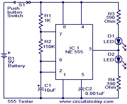
The NE555 timer is configured as an astable multivibrator. When the push button switch S1 is pressed, the LEDs D1 and D2 will flash alternately. When the output is high, D2 will illuminate, and when the output is low,...
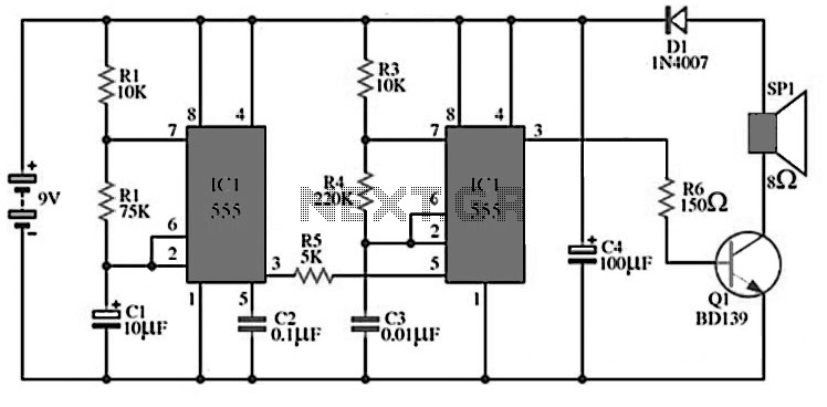
The circuit utilizes IC1 to create an astable multivibrator configuration. It is designed to generate a low-frequency output of approximately 1 Hz at pin 3, which is determined by the resistor values R1, R2 and capacitor C1. The output...
This is a straightforward high-quality PLL FM transmitter with a typical output power of 5 W and a no-tune design. It features RDS/SCA input and audio/MPX input with optional pre-emphasis and can operate with or without a stereo encoder....
The circuit is designed to establish a monitoring and surveillance system for a remote location, functioning as a room monitor or baby alarm. The proposed circuit for the monitoring and surveillance system incorporates various electronic components to ensure reliable operation...
The medical ventilator controller circuit consists of an astable oscillator, a control circuit, and a power supply circuit. The astable oscillator is constructed using resistors R1, R2, a potentiometer RP, capacitors C1, C2, and a time base integrated circuit...
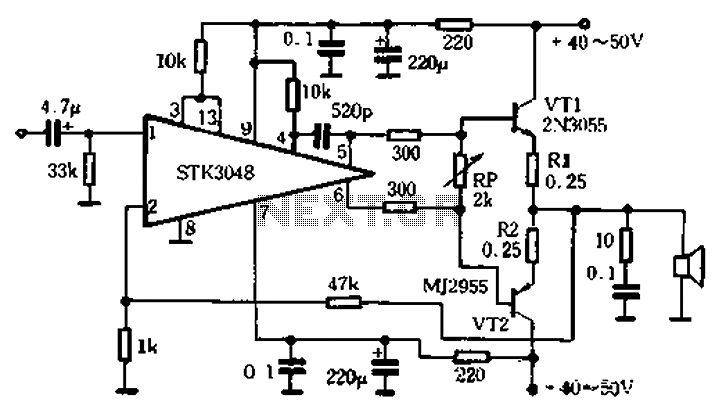
The circuit utilizes the high-power complementary tube STK3048, which operates at high voltage and offers a wide dynamic range. It features an accurate differential input pair, with a common emitter configuration and output terminals connected to a collector constant...